An ESP32 passive PoE (Power over Ethernet) powered circuit board can be very useful for industrial and commercial use. The power of passive PoE is apparent in industrial installations, especially those that are low power such as sensor and control nodes. Given that the usual DC voltage level used with PLC type systems and other standard industrial controllers is almost always less than 50V, it becomes easy to design very simple, custom ESP32 PoE systems that save you the hassle of routing power cables all over the place.
Passive PoE is very simple to work with and is not to be confused with active PoE, which involves smart power controllers and negotiation before powering up a PoE device.
Passive PoE vs Active PoE
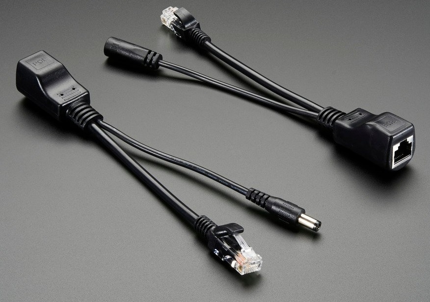
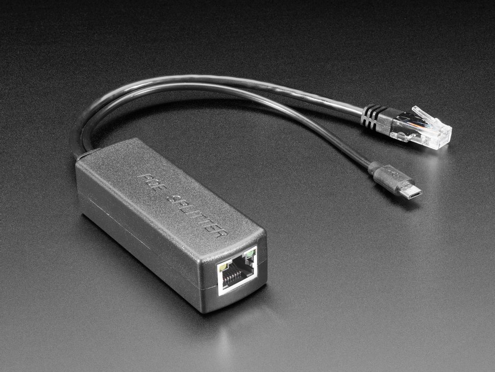
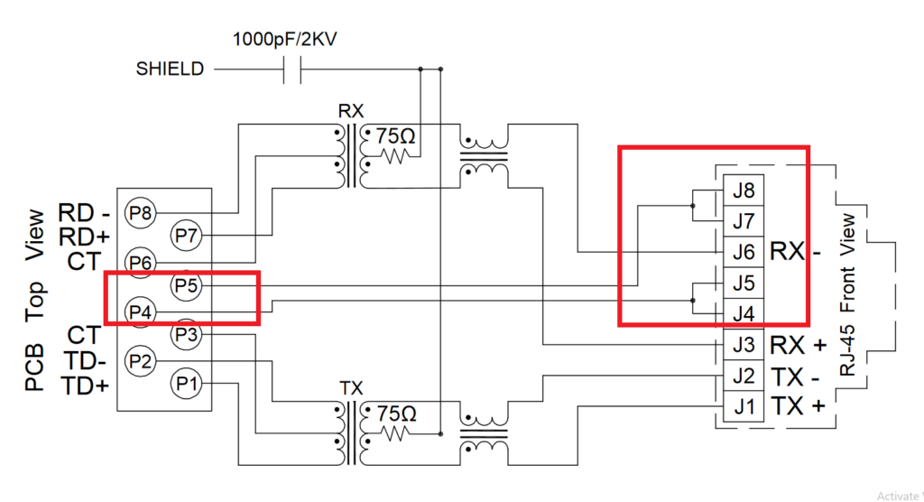
Ethernet Connector and Cabling for Passive PoE
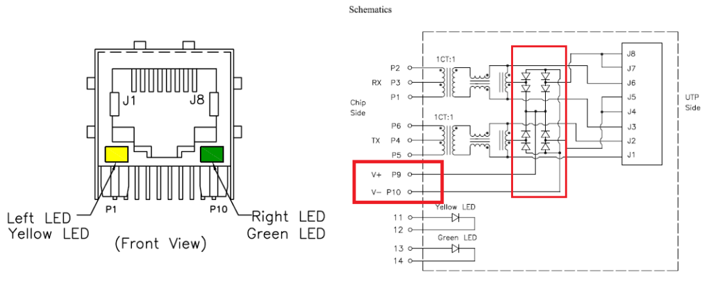
If you compare this connector to another ethernet connector or jack with built-in magnetics and LEDs, you will notice that the regular ethernet connectors will lack the PoE pins highlighted in red above. Those connectors do not expose the power conductors, nor do they contain rectifier diodes within the connector that help with polarity protection in a PoE system.
Passive PoE System - How It Works
- A PoE compatible ethernet jack or connector, preferably with built-in rectifiers
- Ethernet PHY with LAN8720A connected to the ESP32
- Input filtering circuits with spike protection and for PoE DC power smoothing
- A buck converter for stepping down the PoE cable voltage to 5V or 3.3V as needed
- ESP32 itself, and any other peripherals that you want on the system
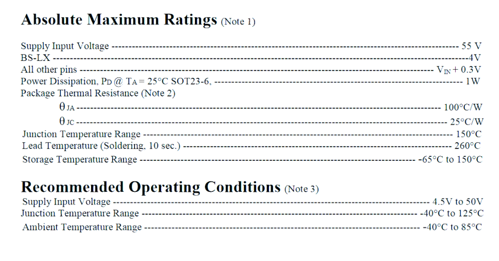
A simple buck converter is usually more than enough for a passive PoE system. For example, here are the absolute maximum ratings for buck converters like SY8401 and SY8291 from Sylergy. These buck converters operate from very high input voltage of over 40 volts and are suitable for using in robust passive PoE applications.
The peak current output of buck converters like this is enough to sustain the spikes that ESP32 causes during WiFi transmission (we have tested this).
Passive PoE Power Block Schematics
Finally, here is the schematic for a very simple DC-DC converter regulator block that steps down the PoE DC voltage to 5V. The 5V can then be fed into the ESP32 via another higher frequency buck converter or a simple LDO.
If you have no use for 5V in your design, you might as well step the PoE input down to 3.3V directly.

Note that the above circuit only displays a simple view of the passive PoE step-down converter that can handle ESP32 consumption requirements.
To make the whole ESP32 passive PoE system work, you will need to add:
- ESP32 ethernet PHY interface using LAN8720 or similar
- More smoothing, if high noise or ripple is expected on the power line (optional)
Impact on ESP32 Ethernet Firmware
Adding PoE, either active or passive, does not involve the ESP32 in any way. The ESP32 will not have to control anything additional and thus no firmware change is necessary.
That being said, some active PoE power management chips might need configuration via IOs or I2C. However, that is not very likely unless you are building very complex or high power systems.
Practical Power Delivery Limitations
Please fill in the Subscription Form in the sidebar so we can keep you updated with our latest articles.
We only mail you less than 2 times a month.
Change Log
- 01 April 2021
– Initial Release - 06 May 2021
– Added section “Practical Power Delivery Limitations”
References
- Reference 1: SY8401 Datasheet
- Reference 2: Adafruit Passive PoE Injector
- Reference 3: Adafruit Active PoE Injector
7 comments
Great article! Really helpful.
I was wondering, do you have a type number or links of the passive PoE ethernet jack?
Thank you in advance
Rick
Thanks! LPJ4112CNL or similar jacks are good. If there is no stock or availability, I just sort ethernet jacks by availability and then look for connectors that expose the PoE power conductors for my use.
Hi,
Take care with SY8291 !
It can only operates over input voltage range from 5V to 40V.
Gonna explote !
Regards
Thank you for repeating that! Always good to check datasheet before copying designs from the internet.
I forgot to mention in the article that the schematic is only meant for 12V and 24V passive PoE (48V passive PoE is very rarely used).
Perfect, just what I needed. But could you help illustrate how to connect the magjack with no internal rectification? Do I simply use a diode-bridge on P4 and P5 to get me PW_P and GND?
Yes, you need to use diode bridges on the pair of pins that is carrying power. Make sure you pick the correct voltage and power rating for the diodes!
Great overview! Passive PoE with ESP32 is a smart solution for low-power industrial nodes. Eliminating extra power wiring simplifies deployment—especially in sensor-heavy environments. Looking forward to more insights on real-world applications!