This article demonstrates a simple ESP32 ethernet example using ESP-IDF and the ESP32 Gateway. The built-in ethernet PHY of the ESP32 is very useful for establishing a high-speed ethernet link in connected industrial and automation applications where modbus TCP and similar links are common.
Wi-Fi is common, but ethernet is still very useful in industrial environments where low latency and reliable data transfer matters. LAN8720 is one of the possible external ethernet PHY chips that you can use – and we have used it for dozens of our designs now, including the ESP32 4G LTE Gateway (gen.1).
This example will work on any LAN8720 based ESP32 board, and you can use this to validate your ESP32 ethernet PCB design.
The main purpose of this article is to walk through an example and the expected output when validating or testing new ESP32 based ethernet hardware.
ESP32 Ethernet Hardware Requirements
There are several ESP32 compatible ethernet interface ICs that you can use, they seem to have more in common than they are different. We favor the LAN8720 because it has widespread support across several platforms and was introduced very early in the ESP32 development environment. LAN8720 is supported by pretty much any ESP32 development environment out there.
This example will work for you as long as you have any LAN8720 based PCB. We are using our ESP32 4G Gateway. The few hardware details that will matter later are listed here.
LAN8720 Oscillator Configuration
There are 2 possible clock configurations for making ESP32 work with LAN8720:
- ESP32 generates 50 MHz ethernet clock
The ESP32 can generate required clock signal via internal PLL, which can then be fed to LAN8720. - External 50 MHz clock used by both ESP32 and LAN8720
This is the approach recommended by Espressif to use RMII PHY with ESP32. In our hardware, GPIO 0 of the ESP32 is used as an input to sync with external 50 MHz phy clock generator. The clock generator is enabled by setting GPIO 12 high. You can read more about ESP32 ethernet clock options here.
Some isolated or buffered ESP32 programmers may strongly drive the IO0 pin of the ESP32 to either 0 or 1 when they are connected. That can either cause high current draw or end up preventing the ethernet clock from working. Removing IO0 connection of the programmer can help if interference occurs and ethernet cannot be initialized.
GPIOs connected to MDIO, MDC, and PHY_POWER
ESP32 RMII ethernet PHY pins are not configurable via GPIO MUX, which means that they will not change across designs. The only GPIOs that vary are MDC, MDIO and a phy power/clock control pin.
For the PCB Artists ESP32 4G Gateway, the pins are connected as mentioned below.
- MDC – GPIO 32
- MDIO – GPIO 18
- PHY enable -GPIO 12
- Reference 50 MHz clock – GPIO 0
LAN8720 logical address
We set the LAN8720 logical address to ‘1’ by pulling PHYAD0 pin of LAN8720 up.
Building the basic ESP32 ethernet example (ESP-IDF)
We recommend setting up ESP-IDF v.5.0.1 for building this example. This is the most recent stable version of ESP-IDF and highly recommended for all new projects.
- For instructions on setting up ESP-IDF 5.0.1, refer to Espressif documentation here.
- Make sure ESP-IDF is configured by building and running
esp-idf/examples/get-started/hello_world - In the terminal, go to the basic ethernet example folder
esp-idf/examples/ethernet/basic - Make sure that the target is set to ESP32 and not some other variant of the chip
idf.py set-target esp32 - Run menuconfig to set hardware-specific configuration
idf.py menuconfig
Go to menuconfig -> Example Configuration and set the following (or settings to match your hardware)

- Save the above configuration and proceed to build and flash the example:
idf.py build flash -b 921600 monitor -p COMx
COMx should be the COM port that your ESP32 programmer is connected to.
The ESP32 Gateway (gen.1) cannot be powered from the programming port. Make sure the board has external DC power before trying to run the ethernet example on it.
Running the ethernet example
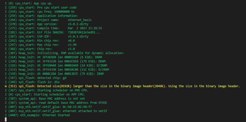
If you had your hardware powered up and connected,the ESP32 should be flashed and this is what you should see on your debug logs if you configured the example correctly and your hardware works well.
The next step is to connect the ESP32 device to a router or computer using an ethernet cable. Make sure that the device you connect the ESP32 Gateway to has DHCP enabled so the ESP32 hardware can obtain an IP address on connection.
If ethernet link is functional but IP address is not obtained, you should see the following in the ESP32 log.

If the cable is unplugged, the log output mentions that the link is down.
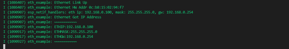
When DHCP is enabled, for example, if you connect the ESP32 ethernet device to a router with internet access, you should see that an IP has been obtained.
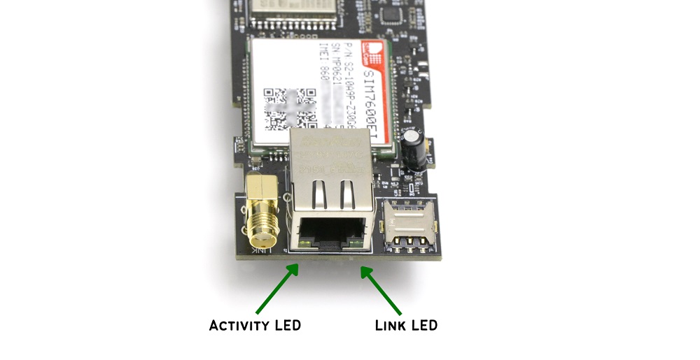
Any time the link is configured in 100 mbps mode, the link LED should light up.
If there is any activity on the ethernet link, you will see the activity LED blinking.
Have Something to Say?
Feel free to ask away via the Live Chat, drop us a message using the Quick Contact form in the sidebar, or leave a comment below.
Change Log
- 19 March 2023
– Initial release