This article outlines how to replace microUSB with USB-C connector in an existing application or new designs. We look at multiple common connector types and how you can modify the design of the application to add USB Type C support.
USB-C or USB Type C connectors have been taking over the market fast – and for good reason. They are not as delicate as a microUSB connectors, they can accept a reversed plug and they also allow for many additional features that modern applications benefit from.
USB 2.0 MicroUSB Connector Pinout
Before you can try to replace an existing microUSB connector, it is very important to understand the difference between the USB Type C and the older microUSB connector.
Let us start by taking a look at the universal microUSB connector pinout and structure. There is rarely any variation across microUSB connectors and the variation will only be with respect to how the connector is mounted or mechanically supported. The pinout should always be the same as shown below.
USB 3.0 microUSB connectors tend to use a 10 pin connector, but we are not going to consider that as those connectors are not nearly as common as the 5-pin USB 2.0 type microUSB connectors.
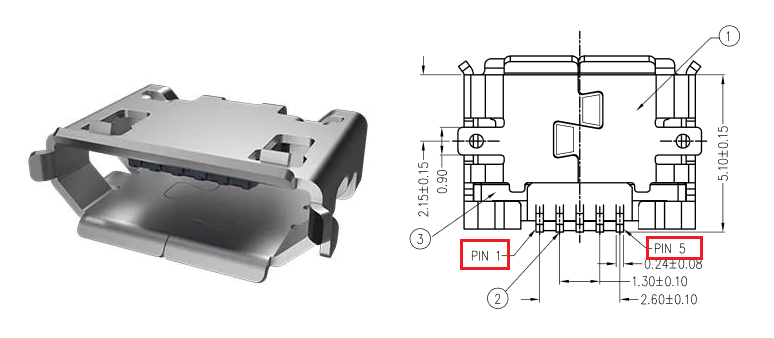
5-pin microUSB connectors as shown above will always have 5 pins and a set of chassis pins or studs that help secure it to the PCB. These 5 pins will be:
- VCC
- D- or DM
- D+ or DP
- ID
- GND
The USB ID pin is the mode detect pin used in USB OTG mode. We can ignore that in USB slave-only devices that use microUSB connector.
USB Type-C or USB-C Connector Pinout
USB-C connectors are not as simple as the microUSB connector. At the very basic level, the USB C type connector is designed for plugging both ways and is not orientation sensitive. To achieve this symmetry the USB-C connector uses mirrored set of pins along both pin rows. This mirrored pin arrangement is shown below.
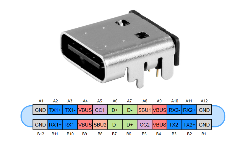
Now if you wanted to replace a simple 5-pin microUSB slave-only USB connector with this one, you can see how that will not really be a drop-in replacement!
However, a lot of these pins are not needed for just using the connector for power or data.
Luckily for us designers, there are many variants of USB-C connectors available in the market to easily replace microUSB with USB-C connectors without forcing you to use 24-pin, fine pitch USB-C connectors that are hard to solder by hand.
We will take a look at some of the pins and their functions as we go through this article.
Case 1: Replace MicroUSB with USB-C for Power Only
Sometimes all you need is to use a USB-C connector instead of a microUSB connector for power delivery to the USB device. This could be a relatively low power device or just a simple charger where you do not really care about the USB data lines because you do not need them at all.
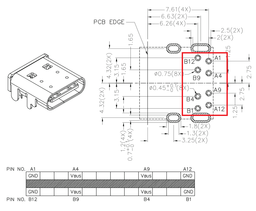
The simple solution here is to use 8-pin or 10-pin USB-C connectors with only power pins.
To extract power from the USB-C connector, you need to access
- Pins A1, A12, B12, B1:
GND - Pins A4, A9, B9, B4:
VBUS - Pins A5, B5:
CC1 and CC2
You can simply short together or connect together all the GND pins and all the VBUS pins and use them for USB power. Simple!
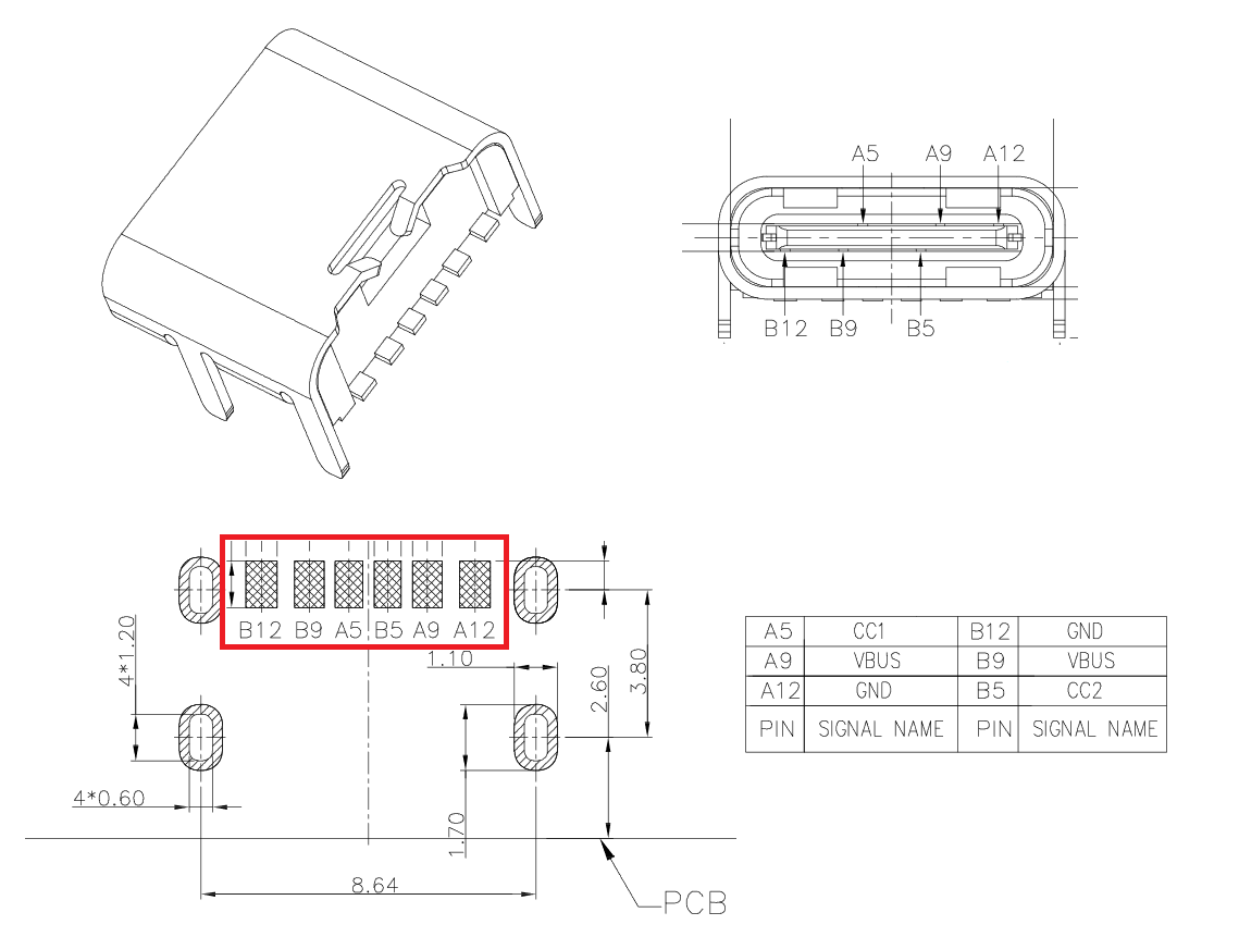
Case 2: Replace MicroUSB with USB-C for Power Only, with CC pins used
There are not a ton a USB-C connectors in the market that just bring out the power pins for you. Many connectors will usually expose CC pins of the connector too.
In fact, the CC pins are compulsory to implement on ALL connectors. Those that do not expose the CC pins just have internal resistors inside the connector to set the proper configuration.
What do you do with the CC1 and CC2 pins?
The CC pins are used for configuration detection purposes. You cannot leave them floating around, or the USB host may not put out the power you need via the USB VBUS pin.
The CC pins contain pull-up or pull-down resistors so that the port configuration can be detected to figure out whether it is a down-stream facing port or upstream-facing port, cable detection and current capability advertisement.
For our case of microUSB USB slave that just needs to draw current, the CC1 and CC2 pins must have a 5.1 Kohm pull-down resistor each.
An example of a connector with VBUS, GND and CBS pins exposed is shown here.
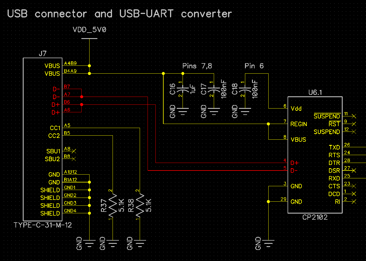
Case 3: Replace MicroUSB with USB-C with Data Lines
To replace microUSB with USB-C connector in an application that needs USB data lines too along with USB power, you need to have a USB-C connector with all pins exposed.
An example of such a connector is the TYPE-C-31-M-12.
Here is a schematic for you to understand how to connect such a connector with a USB slave device controller.
We hope that you are now armed with enough examples and connector part numbers to decide how you can best replace your microUSB with USB-C connector, both in new designs and existing applications!
Please fill in the Subscription Form in the sidebar so we can keep you updated with our latest articles.
We only mail you less than 2 times a month.
Change Log
- Initial Release: 09 December 2020
References
- Reference 1: Amphenol microUSB connector datasheet
- Reference 2: CUI UJC-HP-G-SMT-TR, USB-C power-only connector datasheet
- Reference 3: Korean Hroparts TYPE-C-31-M-17 USB-C connector datasheet
- Reference 4: Microchip AN1953: Introduction to USB-Type C