This article goes through the steps of implementing ESP32 4G modem interface for adding 4G cellular connectivuty to your IoT application design. This article and notes will apply to SIM5360 and SIM7600 series of 3G and 4G modems from Simcom.
However, the schematic blocks will generally apply to all Simcom modems and almost every other cellular modem in the market. They are all very similar electrically.
All cellular modem circuits consist of a few basic blocks, which we will go over:
- Modem power supply
- Modem UART interface (connects to ESP32)
- Modem Control Lines (connects to ESP32)
- SIM Card interface
- Debug Pins or Port
- RF ports for cellular and GNSS or GPS
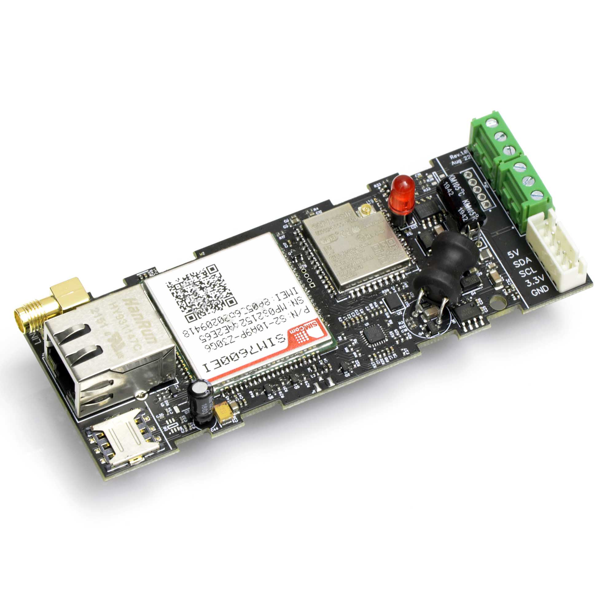
We have used schematic blocks outlined in this article to design several products, such as this ESP32 4G Gateway (one of our new products).
A SIM7600 based Gateway
- -14%
 Select options This product has multiple variants. The options may be chosen on the product page Quick View
ESP32 4G LTE Gateway (Gen.1)
$119.99 – $129.99Price range: $119.99 through $129.99
Modem Power Supply
The ESP32 only requires a 3.3V power supply. However, the cellular modem will need a high current 3.7V power supply. While many modems do work down to 3.5V and you can possibly power both the ESP32 and the 4G modem with 3.5V, it is not recommended because the voltage can dip when both ESP32 and the modem transmit data. This can cause random resets.
So, to interface the ESP32 and 4G modem, you need
- 3.3V @ 500mA power supply for the ESP32
- 3.7V @ 2000mA power supply for the cellular modem
- 1.8V for audio circuits or SIM (modem usually supplies this)
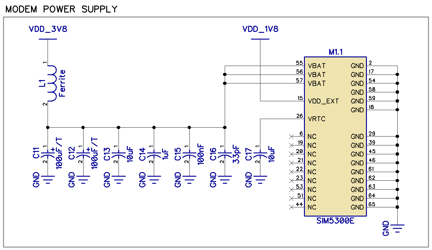
The power supply should be filtered through an 0805 ferrite bead to keep high frequency noise away from power rails. You should use a bead that can handle 2A or higher current.
100uF capacitors are tantalum capacitors located close to the modem. The modem datasheet recommends higher, but I have found 220uF total to be sufficient when using a good DC-DC buck converter or high capacity LiPo cell.
The 1.8V power rail is sourced by the modem.
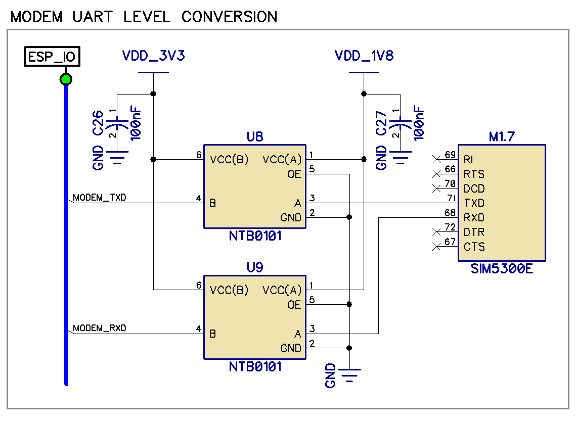
UART Connections, ESP32 to Modem
The ESP32 modem UART link can consist of the Rx and Tx lines only, or a full serial port with flow control. Flow control can be unnecessary in most cases if the serial data rate is low and the application only sends short chunks of data out.
However, something important to note here is that the ESP32 operates at 3.3V logic levels. A cellular modem will work with 1.8V logic and can be damaged if 3.3V is fed into a 1.8V modem pin.
You should therefore use a logic level converter.
A design is shown here for your reference.
ESP32 and Modem Control Lines
Other than the UART link pins needed to talk to the modem, the ESP32 also needs to access some other pins to control the basic modem functions or monitor for events.
- STATUS pin: Signals whether the modem has powered up and is ready to start communicating
- NETLIGHT pin: Used to indicate network activity and status
- RESET pin: Used to reset the modem
- PWRKEY pin: A key press input that turns the modem on and off, equivalent to a software command
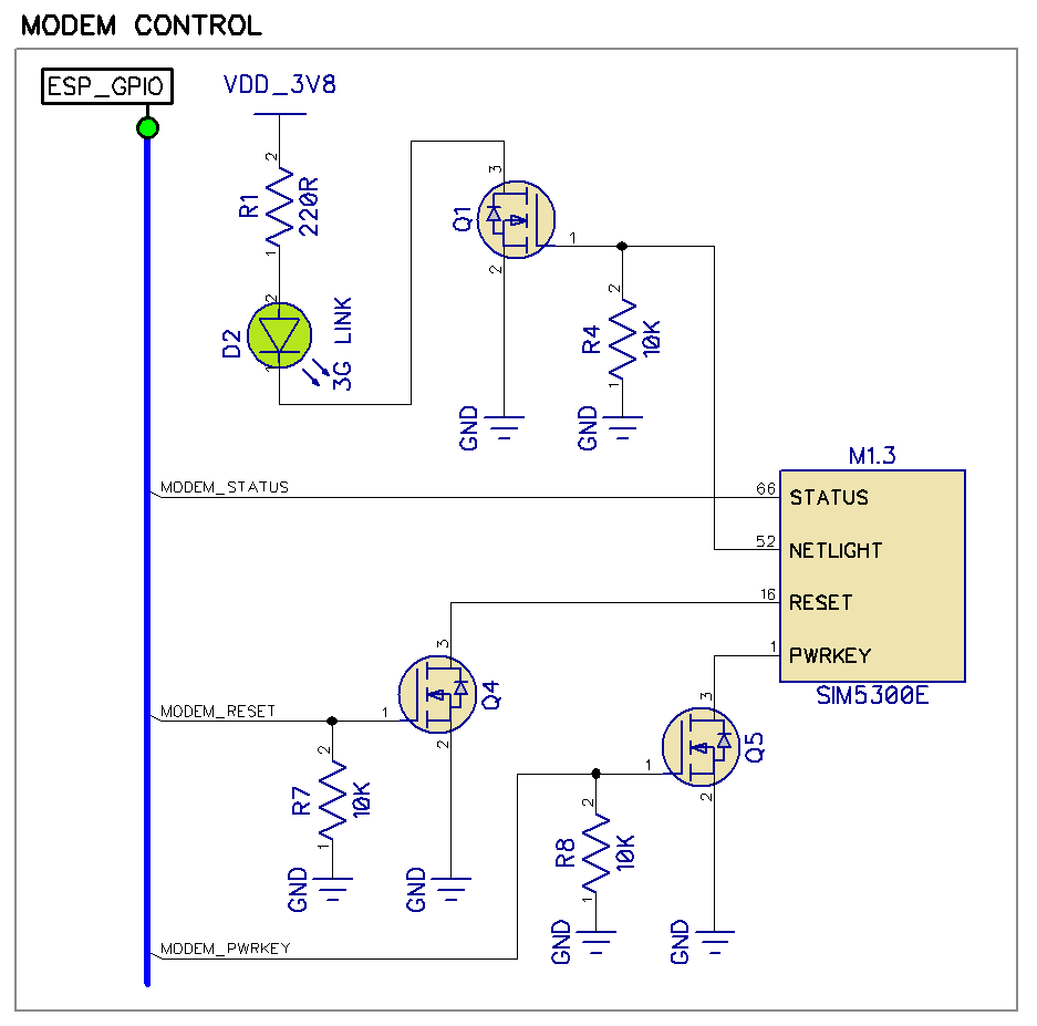
Again, the MOSFETs serve as logic level translators and isolators. The modem pins are internally pulled up to 1.8V and the MOSFETs make sure that the pins can only be pulled low and there is no possibility of feeding 3.3V back into the modem via the control pins.
SIM Card Connector
You can also use an MFF2 chip SIM instead of the usual nano, micro, or regular SIM cards.
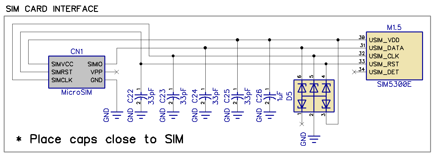
If you are using a chip type SIM or if your SIM card connector ensures that there can be no ESD into the circuit, you can skip the ESD protection.
The 33pF caps should still be left in there because they help reduce interference and noise from the cellular modem itself. Removing them can cause problems sometimes.
Am improperly designed SIM interface will often result in random SIM Errors during operation.
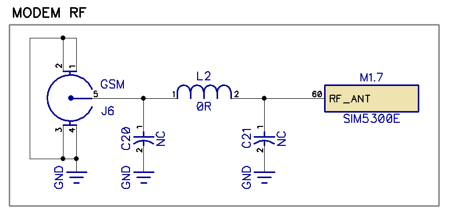
Modem RF Pins
A modem will have RF pins like BT/Wi-Fi, LTE and auxillary LTE for antenna diversity, or GNDD antenna input.
Like any other RF chip that connects to an antenna, the modems will need to be matched to the antenna via a pi-matching network. During the prototype phase, you can get away with leaving the pi-matching network out and just using a 0 ohm resistor to connect the antenna to the modem directly.
Almost all modems I have seen come with a 50 ohm output impedance and can be connected to a 50 ohm antenna directly for prototyping.
However, in production, you need to get the antenna matched. Drop us a message if you need help with antenna tuning.
Please fill in the Subscription Form in the sidebar so we can keep you updated with our latest articles.
We only mail you less than 2 times a month.
Change Log
- Initial Release: 04 July 2021
References
- Reference 1: SIM7600 Datasheet