The VLSI solution VS1000 is a very versatile and useful audio solution whether you need to make an audio player or even if you wanted to implement a rather complex system with regular system functions and audio functions. However, the VS1000 does not have a dedicated set of line out pins, which might make things difficult if you have to connect the chip to an external audio equipment or speaker driver. In this article, we go through some VS1000 line out implementations and an example schematic on how you could add an external amplifier to the VS1000 line out.
VS1000 Line Out Schematic
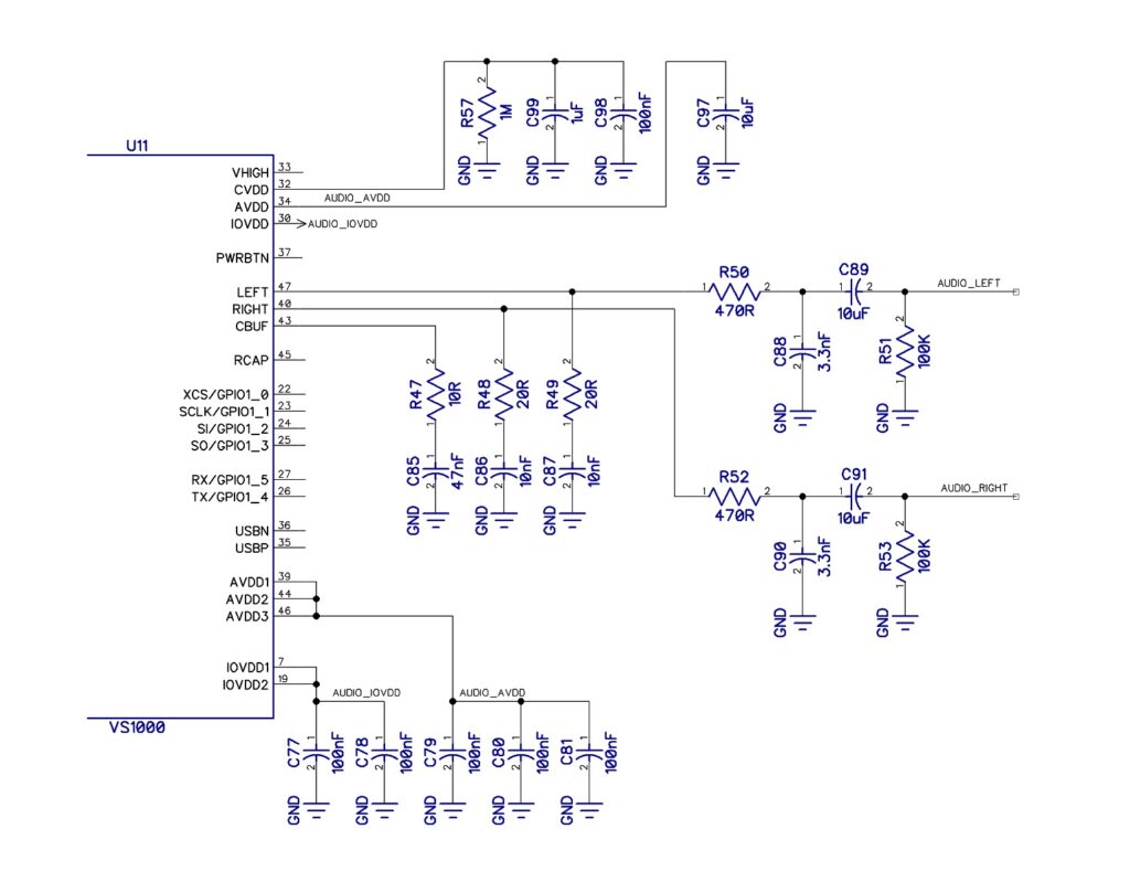
Here is a version of the VS1000 line out derived from the headphone outputs. Some things to note about the schematic:
- R47-C85 RC load is still required on the unused CBUF pin for maintaining stability.
- The CBUF pin has been left unused because it only provides a 1.2V output used to drive headphones. Not that even though CBUF is usually connected to the headphone COM pin, that does NOT make the CBUF pin the system ground!
- R51 and R53 pull the output down to ground when the VS1000 is not actively driving the audio output. That way you will have much less noise in the line output or the audio amplifier IC connected to the line out.
- R50-C88 and R52-C90 make a simple RC low pass filter network that help in grounding any digital noise from the VS1000. They are highly recommended, or you could end up with a LOT of noise in the output audio.
- C89 and C91 make up the output coupling capacitors. It is usually good to have them to block any DC voltage. The value depends on the input impedance of the device that connects to the line out… but 1uF to 10uF is a good value. Most devices that connect to the line out will usually have an input impedance of at least 10K. Using a larger coupling capacitor will give you good low frequency characteristics.
VS1000 Line Out and Audio Amplifier Schematic
Here is yet another very clear and helpful schematic that shows you how to derive the VS1000 line out signals from the headphone outputs.
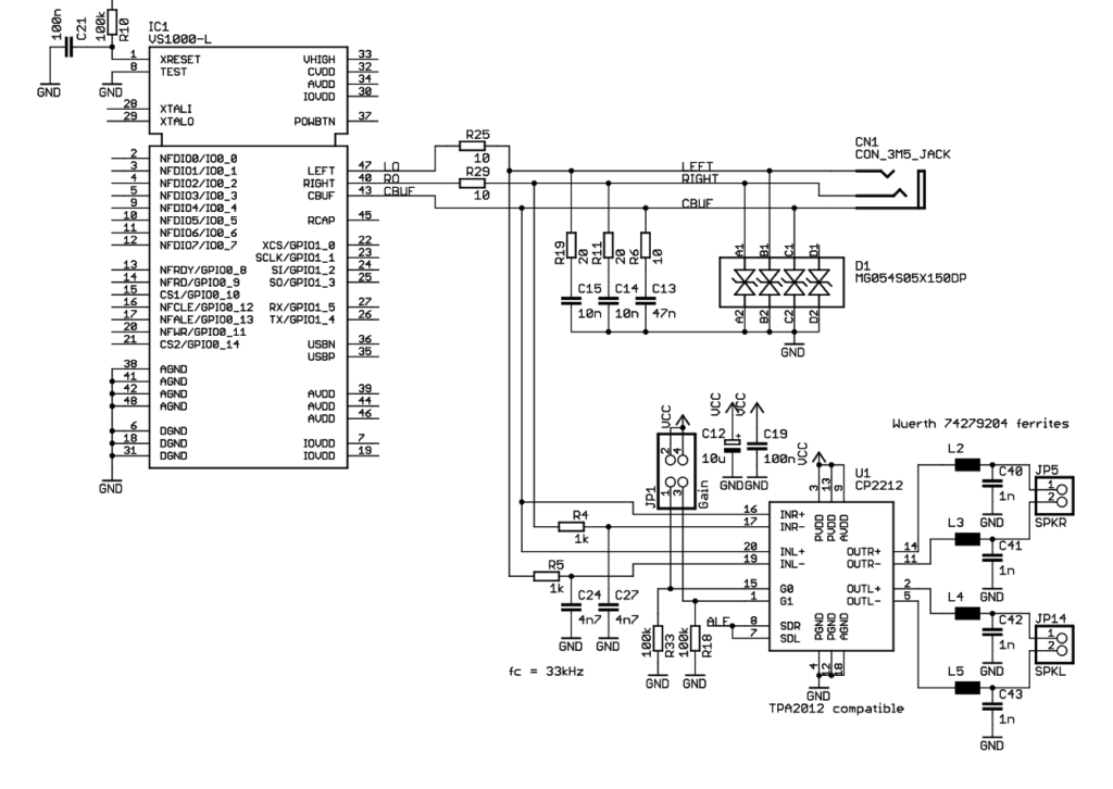
As you can see, we have stripped down the schematic and removed everything unrelated to the audio lines to keep things clear. The major segments in this schematic are:
- Stability and ESD tolerance:
LEFT, RIGHT, and CBUF pins must have a certain R-C load for stability and ESD performance, as is directly specified in the datasheet. In the schematic, R6, R11, R19, C13, C14, and C15 make up this network. - Low pass filter to remove DAC digital noise:
R4-C27 and R5-C24 make up the filter. You should consult the datasheet of the audio amplifier to see what cut-off frequency will work best for the specific audio amplifier chip. Here a cut-off frequency of 33kHz is used. If you lowered it, you could get cleaner audio at the cost of losing gain in the treble region of your audio. - Capacitive coupling to the audio amplifier:
Not shown here, but if your audio amplifier datasheet recommends it, you should at least leave footprints for DC blocking capacitors at the left and right channel inputs of your audio amplifier. For high impedance input amplifiers, a DC blocker should not be needed, but then some amplifiers have issues with power dissipation and distortion if you held the input pins at a certain common mode voltage.
Some tips for high quality audio!
Just making it work is never enough. Here is how you can get the best audio quality from line output or an amplifier IC that amplifies the VS1000 output.
- Try to power the VS1000 and audio amplifier IC using different voltage levels, with the audio IC preferably powered off a different regulator and run using a voltage higher than that of VS1000.
- Make sure you calculate the channel low pass filter R and C values carefully. If you set it too low, you lose the treble in the audio. If you set it too high, it can cause a lot of high pitch noise.
- Remember to look at the amplifier IC datasheet to make sure it can accept the whole output audio frequency range without distortion. If the amplifier needs a certain type of input filter, make sure you have it implemented!
- Me mindful of the input impedance of the audio amplifier IC. If you need pre-amplifiers, you should add some before driving a very high power and low input impedance audio stage.
- Letting the line output go out to an external system? Do not forget the ESD diodes!
- If you are feeding the line output into professional audio gear, make sure you can drive 600 ohm input impedance on many of those devices. While devices try to stay over 1K ohm with their line input impedance, 600 ohm is the standard for professional high performance equipment.
Change Log
- Initial Release: 08 December 2020