The ESP32 WiFi/BT SoC from Espressif Systems supports wired ethernet along with wireless networking, which could be a huge advantage for applications that need wired connectivity. Ethernet is still a very popular standard for building and industrial automation. The ESP32 ethernet feature lets you mix wired and wireless connectivity with one low cost design.
While it is not exactly low power, it does offer advantages like PoE (Power over Ethernet), which can be used to power ESP32 directly off the ethernet cable. This saves installation costs and allows ESP32 to be a standalone ethernet device.
ESP32 ethernet PHY interface schematic
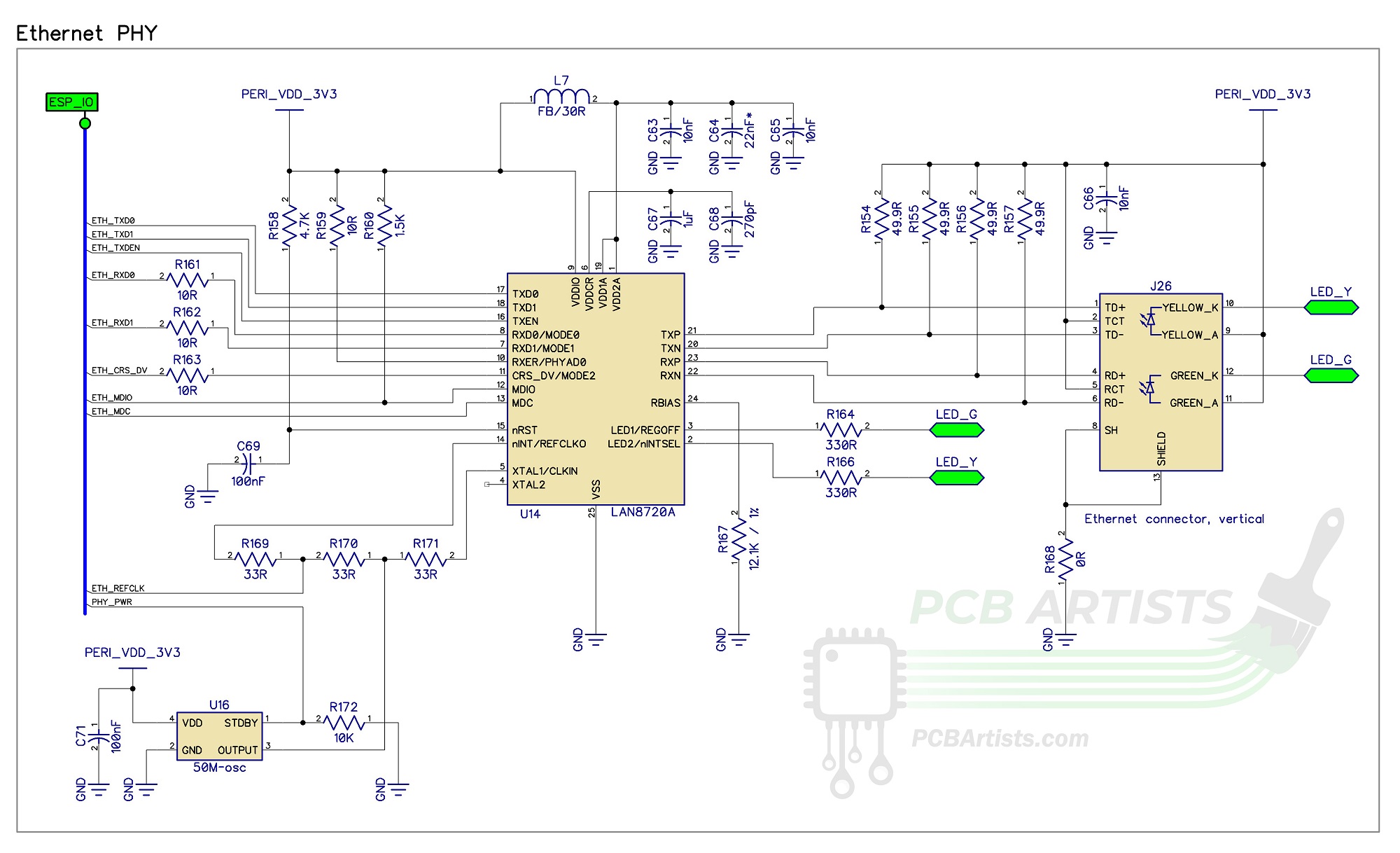
The ESP32 ethernet phy interface is shown in the schematic above. It mainly consists of three sections:
- The PHY chip or interface
- The 50 MHz oscillator
- Jack and magnetics
The main sections that you need to pay attention to for proper operation are:
- Pull-up resistors on ESP32 side of the PHY chip.
- Series termination resistors for reducing signal reflection and ringing.
- The 50 ohm pullups on the ethernet jack side of the PHY chip.
- Proper magnetic jack. Most ethernet jacks are low cost and do not contain any magnetics… you cannot use those directly. You will need external inductive components for using plain old RJ-45 connectors.
ESP32 resources needed for ethernet
Ethernet is rather demanding in terms of GPIO requirements. The IO MUX of the ESP32 cannot be used to flexibly configure GPIOs for ethernet interface. You must connect the specified ESP32 GPIOs to the ethernet PHY chip (the PHY chip could be a LAN8720 or LAN8710, for example).
The GPIOs you will need to reserve for ethernet are listed below for reference (excluding the clock pin):
| ESP32 GPIO | Ethernet PHY IO |
| GPIO 21 | TXEN |
| GPIO 19 | TXD0 |
| GPIO 22 | TXD1 |
| GPIO 27 | CRS_DV |
| GPIO 25 | RXD0 |
| GPIO 26 | RXD1 |
| GPIO 23 | MDC |
| GPIO 18 | MDIO |
Finally, let us not forget the ethernet clock pin. The GPIO0 of ESP32 will be connected either to a common clock source or will be sourcing the internal APLL clock to the PHY chip.
In either case, GPIO0 will be used up and the audio PLL may not be available at the same time as the ethernet interface.
External oscillator for ESP32 ethernet PHY
- 50MHz external clock IC
- ESP32 APLL generating the required 50MHz
PCB design and layout
- Pair up differential traces
- Make sure all series termination resistors on ethernet GPIO lines are placed close to ESP32.
- Length matching is not necessary, but the trace lengths should not vary wildly.
- GPIO0 or whatever other GPIO carries the 50 MHz clock signal must have as little capacitive loading as possible.
- The clock trace should be around the same length as the other signal lines.
- The traces connecting the ethernet jack and PHY interface chip should preferably be short. They should be routed as differential pairs.
References
Reference 1: LAN8720 datasheet
Reference 2: ESP32 datasheet
Reference 3: ESP32-EVB documentation
Reference 4: ESP32 AT firmware documentation (ethernet)