ESP32 CP2102 programmers are very common in the market. You can find them in almost any hobbyist store online. However, sometimes it really helps to integrate the programmer section into your application design – be it development boards or final products. A circuit like this can safely allow the user to upgrade firmware of the product with no risk of “bricking” it. In high volume production runs, adding this ESP32 CP2102 programmer block adds to BoM cost by barely a dollar.
Also, you can use this CP2102 schematic to make an ESP8266 programmer.
ESP32 CP2102 Programmer Schematic
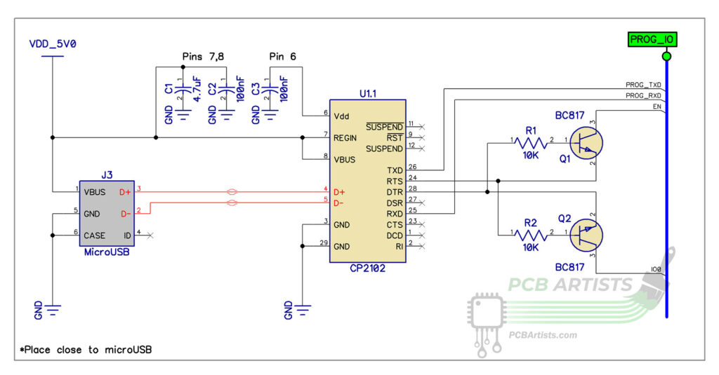
Left to right, the above schematic contains a USB connector. It could be any regular mini-USB or micro-USB connector, they all have similar pinouts.
The USB type C connectors will have more pins, we are not getting into type C connector based schematics in this post, but you can easily use a USB type-C connector instead of the usual microUSB.
CP2102 power configuration options
In the programmer schematic presented above, the CP2102 is configured to bus-powered mode. In the bus-powered mode, the chip gets its power from the USB port.
About using bus-powered configuration:
- This configuration is suitable for cases where you want the CP2102 to activate only when the USB connector is plugged in. If your application is powering the ESP32 or ESP8266 from another source such as a LiPo battery pack, this mode is the one you should use. That will ensure that the CP2102 does not run your battery down for no reason.
- Note that the total capacitance on the USB power lines should be 4.7uF or less in typical applications. This is to ensure that the short circuit or overcurrent protection inside the USB host does not trip up when the decoupling caps draw a surge of current on connection.
- If the rest of the circuit uses power from the same USB port, make sure you account for the total power consumption and keep it under the maximum specified USB host current capability.
About using self-powered configuration:
- This configuration is suitable when you have a mains powered application or an application where power consumption is not very relevant to you. You can connect REGIN pin of CP2102 to this power source (consult the datasheet for voltage limitations). VDD and REGIN can also be tied together if the circuit can provide a well filtered 3.3V.
- VBUS should still connect to the USB connector power pin so that the CP2102 can enumerate when it detects presence of a physicall USB connection.
How auto-program circuit works when programming ESP32 or ESP8266
The auto-reset circuit uses the state of RTS and DTR pins to determine the state of EN and IO0 pins of the connected ESP32 or ESP8266.
Here is a table of the pin states and corresponding EN and IO0 levels, assuming that IO0 and EN and pulled up in the ESP32 or ESP8266 system being programmed:
| RTS | DTR | IO0 | EN |
| Low | Low | High | High |
| Low | High | High | Low |
| High | Low | Low | High |
| High | High | High | High |
The above table might confuse you a little, because it cannot pull both IO0 and EN low at the same time (which is needed for changing modes on the ESP32 or ESP8266). The secret to that is the capacitance on the EN pin that is required in all circuits.
Make sure that you have at least 0.1uF capacitance on the EN pin for this auto-programmer circuit to work reliably.
When there is sufficient capacitance on the EN pin to hold it low for a while, the programmer pulls IO0 low and by the time the EN pin rises, the ESP reads a low level on IO0 and boots into programming mode. Clever little trick?
Change Log
- Initial Release: 17 October 2020
References
- Reference 1: ESP auto program logic forum post
- Reference 2: ESP32 datasheet
- Reference 3: ESP32-DevKitC schematics
2 comments
According to the datasheet of the CP2102N (https://www.mouser.de/datasheet/2/368/cp2102n-datasheet-1082647.pdf) VBUS must be connected with a voltage divider to the power supply. In your wiring above you could damage the CP2102N or do I misinterpret the datasheet?
The schematic above is based on a CP2102, not a CP2102N! The 2102N series has VIO for IO voltage levels.
From a quick look at the CP2102N datasheet, I think what they mean to say is that the VBUS (or any other digital IO pin) must not be more than VIO + 2.5V.
If you had a 1.8V controller connected to the CP2102N, then IO set IO voltage to 1.8V, the VBUS being fed directly from USB will go over absolute maximum specs given in Table 3.10.
So you should be alright without divider if you are using the CP2102N with 5V and 3.3V logic levels and always powered on (as is the case with ESP32 chips).
Also, the CP2102-GMR datasheet explains it better. The resistor divider prevents problems when VIO is 0 but VBUS is still present… because max VBUS will be 2.5V if VIO = 0V.
Hope that helped!