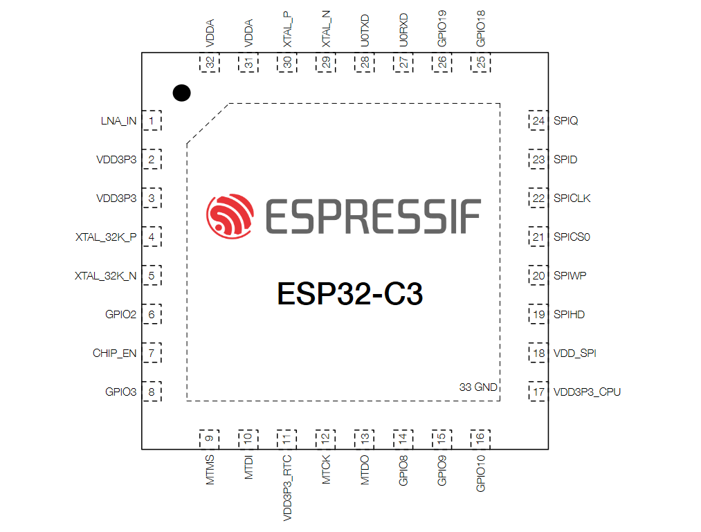
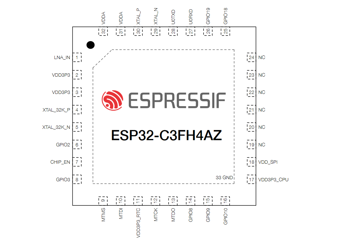
ESP32-C3 is a tiny little chip, which makes every ESP32-C3 GPIO a very valuable resource for hardware designers.
I often design ESP32 based PCBs. ESP32-C3 based PCBs have picked up quite a bit of momentum lately. Instead of reading through the datasheet every time to figure out what GPIOs do what, here is my list of notes that I use to refer to when designing ESP32-C3 schematics. The official documentation contains a Hardware Reference section that can be useful for getting started.
As a general summary, the GPIOs on the ESP32-C3 can be summarized as follows:
- 10 GPIOs – completely flexible
- 2 GPIOs – used for RxD and TxD, may be re-used
- 7 GPIOs – shared with flash, 2 can be saved with DIO external flash, 1 more can be saved with external flash power
- 3 GPIOs – flexible but must be ‘high’ on reset because they are strapping pins


ESP32-C3 Strapping Pins and Usage Notes
Strapping pins are extremely important to take care of when you are designing a custom ESP32-C3 PCB. I would recommend adding a test point to these so you can troubleshoot boot and flashing related issues later.
Connecting the wrong signals to strapping pins can drive them to incorrect states, causing the ESP32-C3 to not boot or flash.
GPIO 2 [strapping] [RTC]
- Must be HIGH during reset in all cases
- If this pin goes low during reset, either flash execution or UART flashing may not work
- RTC domain, can be used for ADC
GPIO 8 - [strapping]
- Must be HIGH during reset in all cases
- UART flashing may not work if this pin goes low during reset
GPIO 9 - [internal PU] [strapping]
- Works as normal GPIOs after reset
- HIGH – SPI Boot
LOW – UART Download - Equivalent to IO0 of ESP32 chip, where it must be high for regular execution and low to flash an application
ESP32-C3 GPIO shared with Flash Memory
The ESP32-C3 has no embedded flash like most other MCUs tend to have. The only way to execute non-volatile code on an ESP32-C3 is to have an external flash chip connected to it.
Some variations of the C3 may come with flash chip integrated internally. This should still be treated as an external flash being connected – just that you do not have control over it.
GPIO 11 - Flash Power Supply
- Acts as flash power supply output by default. Can only be used as GPIO if flash is externally powered.
- On ESP32-C3 with integrated flash chip, this GPIO is unavailable to use as regular GPIO.
GPIO 12 - Flash HD
- Can be used as GPIO if external flash is connected in DIO mode
- Cannot be used as GPIO for ESP32-C3 with internal flash
GPIO 13 - Flash WP
- Can be used as GPIO if external flash is connected in DIO mode
- Cannot be used as GPIO for ESP32-C3 with internal flash
GPIO 14 - Flash CS
- Cannot be used for anything other than flash
GPIO 15 - Flash SCLK
- Cannot be used for anything other than flash
GPIO 16 - Flash MISO
- Cannot be used for anything other than flash
GPIO 17 - Flash MOSI
- Cannot be used for anything other than flash
Other ESP32-C3 GPIOs - General Purpose
These GPIOs may be used more flexibly and do not have as many restrictions associated with them. Some are RTC domain GPIOs and the others are regular GPIOs.
GPIO 0 [RTC]
- Defaults to GPIO
- May be used for 32 kHz crystal or ADC input
- Capable of RTC functions
GPIO 1 [RTC]
- Defaults to GPIO
- May be used for 32 kHz crystal or ADC input
- Capable of RTC functions
GPIO 3 [RTC]
- Defaults to GPIO
- Capable of RTC functions and ADC
GPIO 4 [RTC]
- Defaults to JTAG MTMS
- Capable of RTC functions and ADC
GPIO 5 [RTC]
- Defaults to JTAG MTDI
- Capable of RTC functions and ADC
GPIO 6
- Defaults to JTAG MTCK
GPIO 7
- Defaults to JTAG MTDO
GPIO 10
- Defaults to GPIO
GPIO 18
- Defaults to USB D-
GPIO 19
- Defaults to USB D+, with internal USB pull-up enabled
GPIO 20 - RxD for UART download and logs
- Defaults to RxD for flashing firmware
- May be used for other passive applications if a programmer is not always connected
- If USB-UART bridge does not drive this pin with high current, this pin may be used for LED indicator, debounced button, etc
GPIO 21 - TxD for UART download and logs
- Defaults to TxD for flashing firmware
- May be used for LED or other indicators that may be driven when logs are not always required to be printed
Feel free to ask away via the Quick Contact form in the sidebar, or leave a comment below.
Change Log
- 29 January 2023
– Initial Release