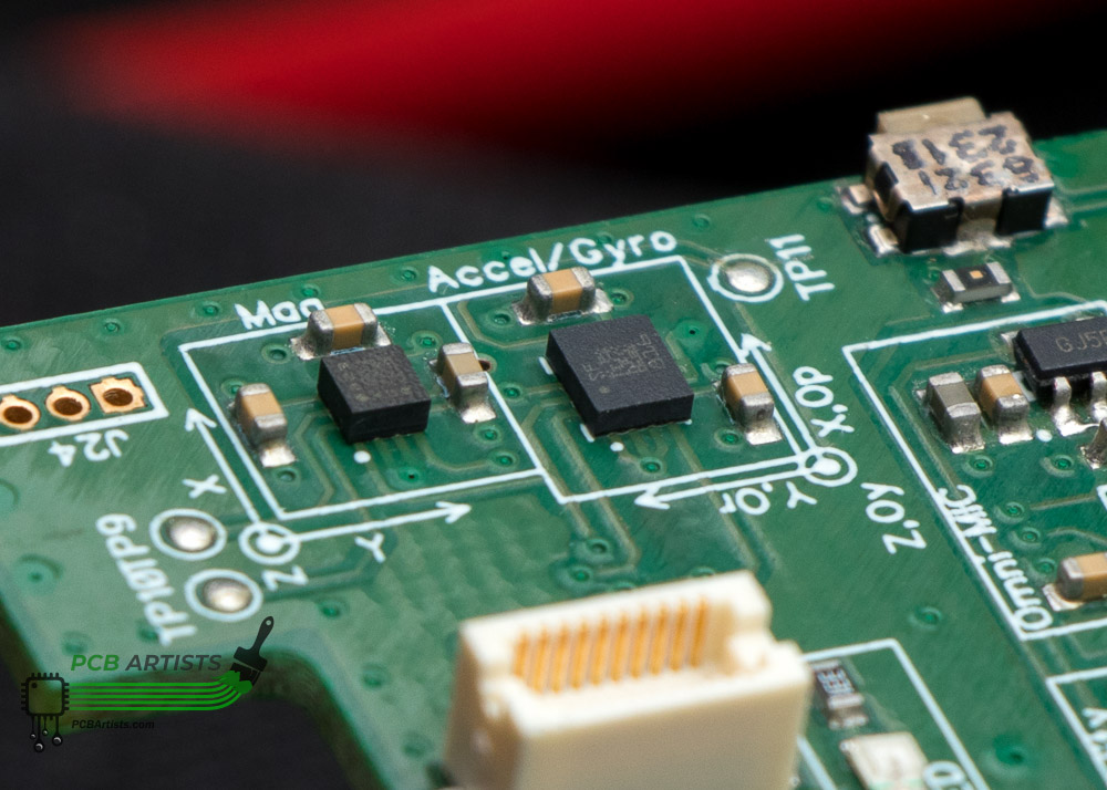
The LIS3DH triple axis accelerometer by ST Micro is one of the popular, low cost and extremely low power MEMS accelerometers in the market today. It does carry the weight of ST Micro brand and is a much prefered device when compared to equivalent no-name brand Chinese accelerometers. We have used the LIS3DH in many of our low cost devices and it works really well for a variety of reasons.
However, we admit that development with LIS3DH is not always as smooth as you would imagine it to be. The datasheet definitely is well documented and there is an application note on how to use the LIS3DH and its advanced functions.We still faced problems with the LIS3DH interrupt generation at first.

LIS3DH interrupt not working - the usual problem
You would be surprised by the number of people who have posted around in forums for the last decade seeking answers to this issue! The LIS3DH interrupt not working is an issue that could be caused by a number of reasons, including configuration issues and simple hardware design issues.
What might potentially be wrong with your particular setup that is causing the LIS3DH interrupt lines to not get asserted are listed below for your help.
The I2C interface may not be working properly
- The Device ID register of the LIS3DH should return the appropriate value. That confirms that you can address and read the device.
- You should write a configuration register or some other read/write type register and read it back. It should match so you know that you can write to the LIS3DH.
Ensure proper MCU GPIO mode
Again, a no-brainer, but it is important to note that the interrupt output pins of the LIS3DH are NOT open-drain type output. The LIS3DH can drive the interrupt pin high and low with good current capacity and you should not use a pull-up or pull-down resistor with the interrupt pins.
Also, if your MCU GPIO is accidentally configured to act as an output, it can potentially fry your accelerometer, or the MCU itself, or both.
Make sure interrupt pin latch setting is correct
The LIS3DH can either latch an interrupt or not latch it. This depends on the value of register CTRL_REG5 (24h). When the interrupt is set to not latch, the interrupt pin will just momentarily (in the order of milliseconds) toggle to indicate an interrupt event. If your MCU code polls the interrupt pin, it might miss the interrupt signal.
When the interrupt is latched, the LIS3DH will keep the interrupt line asserted as long as you don’t read INT1_SRC and INT2_SRC for INT1 and INT2 pins, respectively. So to let the LIS3DH indicate any further interrupts, you need to read the register and reset the interrupt pin state after every interrupt event.
Double-check the interrupt status register
If the above steps failed to get you a solution, you can try reading out interrupt status registers to check that you are actually getting interrupt events. For example, you can read INT1_SRC to check if bit 6 (IA) is set. If it is, this means that interrupt is actually generated but not reported to the INT pin.
You can now look at other issues – LIS3DH settings might not be linking interrupt to the INT1 pin properly, or you might not be reading the MCU GPIO correctly.
Ensure reasonable interrupt criteria
You might have forgotten to enable measurement of an axis of interest as well.
Finally, remember that there is an offset error of +-40mg in the accelerometer readings. Remember to set interrupt threshold away from extreme values like 0 and full-scale readout. This prevents false triggering.
Don't make interrupts "always on"
You can set the LIS3DH to generate an interrupt when acceleration along a certain axis crosses a particular threshold. If you enable interrupt to be active for both “above threshold” and “under threshold” events, you might see the interrupt pin to be always on.
Still stuck?
This problem could have something to do with your hardware design. MEMS are sensitive devices and factors like how it was soldered and stress levels on the PCB can cause serious problems.
Please feel free to drop us a message should you require any consulting assistance with hardware or firmware development!