The PCB Artists ZMOD4510 module UART interface makes it extremely easy to interface with any host MCU – including the STM32 series. Here are some notes on interfacing ZMOD4510 module with STM32 MCU based boards.
Note that not all STM32 MCUs are the same. However, if you are using STM32 CubeMX or HAL and LL APIs, code can be fairly portable between different STM32 series.
STM32 Board Used in this Example
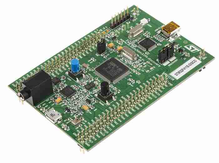
We used an STM32F411 Discovery development board from ST Micro to develop and test this example code. The following sections will walk you through the process of setting up a project and running some example code to try out our ZMOD4510 module.
Creating the CubeIDE Project
You can easily create a project in STM32 CubeMX or CubeIDE. Cube IDE not just sets the development environment up, but also lets you build and debug your example on the target board. This gives you a free all-in-one development environment and we highly recommend this arrangement.
1. Check your STM32 hardware schematics
You will need an UART peripheral (RXD and TXD pins only) for communicating with the ZMOD4510 module.
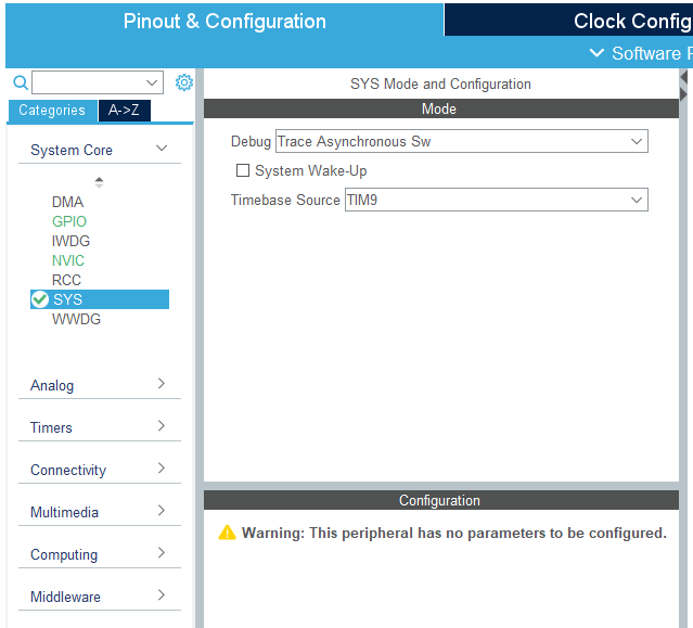
2. Enable debugging interface (SWD and SWO)
This example code uses the SWO output to print out values read from the ZMOD4510 module. If your STM32 hardware does not have a display or terminal connected, you can either watch ZMOD4510 readings by viewing live variables in CubeIDE or by using SWO.
Enable SWO and SWD as follows. If you need to print out debug strings or ZMOD4510 readings on your display, please follow this article to enable SWO viewer.
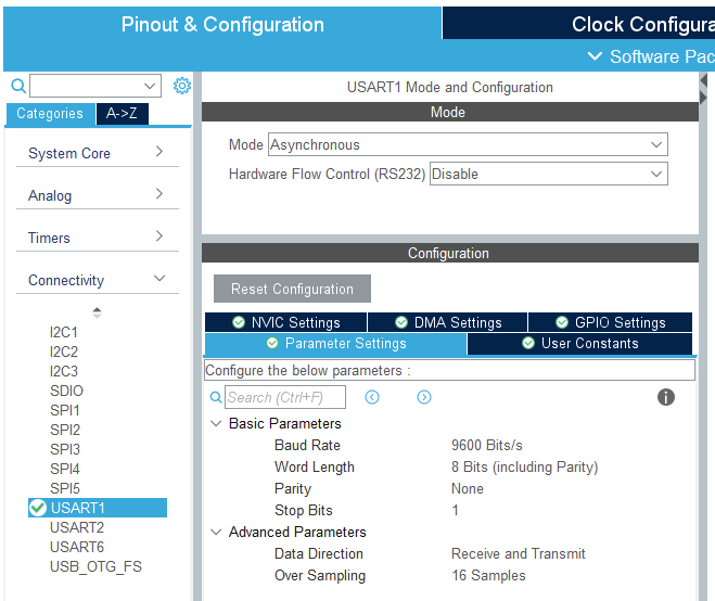
3. Select UART pins for interfacing ZMOD4510 module with STM32
We selected USART1 TX (PB6) and USART1 RX (PB7), which is otherwise unused on the STM32F411 Discovery board.

The appropriate settings for the UART peripheral are shown below. Note that the default version of the ZMOD4510 module uses UART data configuration of 9600-8-N-1.
Source code for communicating with ZMOD4510 Module
Now that you have set STM32 CubeMX project up, you can try to build the blank project and deploy on target board to make sure that it builds and works.
The code snippets below describe important parts of the example code and what they do. Before you take a look at the code, here is the GitHub repository for the example source code for interfacing STM32 with ZMOD4510 module:
Here are the important files that you need to integrate in your own application:
- zmod4510.c – C file for interface functions
- zmod4510.h – H file with basic documentation on all interface functions
- user_main.c – example to power up sensor, start sampling and fetch parameters every 5 seconds
#include "main.h"
#include "user_main.h"
#include "zmod4510.h"

// Extern UART handle as generated by CubeMX in main.c
extern UART_HandleTypeDef huart1;

// Float variables to store latest values
// You can add a live watch on these to monitor values through debugger
float aqi, no2, o3;

void user_main (void)
{
    uint8_t id[10];

    // Initialize ZMOD4510 with default stabilization sample count
    ZMOD_ERR_CHECK (zmod4510_setup (&huart1, 0), Error_Handler);
    // Get 32-bit unique ZMOD4510 module ID
    ZMOD_ERR_CHECK (zmod4510_get_id (&huart1, id), Error_Handler);
    // Start sampling
    ZMOD_ERR_CHECK (zmod4510_activate (&huart1, 1), Error_Handler);

    while (1)
    {
        // Fetch AQI value as float
    	ZMOD_ERR_CHECK (zmod4510_get_aqi (&huart1, &aqi), Error_Handler);
    	// Fetch NO2 ppb value as float
    	ZMOD_ERR_CHECK (zmod4510_get_no2 (&huart1, &no2), Error_Handler);
    	// Fetch O3 ppb value as float
    	ZMOD_ERR_CHECK (zmod4510_get_o3 (&huart1, &o3), Error_Handler);

    	// Loop again after 5 seconds
    	HAL_Delay (5000);
    }
}
The ZMOD4510 library contains required functions and some other functions that are optional. The above C program is the minimum code needed to set up the ZMO4510 module and fetch AQI data from it.
zmod4510_setup() function initializes the ZMOD4510 module with stabilization sample count and reads module ID to make sure that the module is ready for operation. Stabilization sample count is the number of 1-minute sample cycles that ZMOD4510 uses to stabilize its readings. Valid readings are only produced after the end of stabilization. Recommended count is 10 to 60.
zmod4510_get_id() fetches the module ID as 8 ASCII characters. By adding a NULL or ‘\0’ as the 9th byte, you can make the ID a string.
zmod4510_activate() activates or deactivates the module based on the argument passed. Activation starts the sampling system. Deactivation puts the module in low power mode and pauses sampling. Settings such as stabilization sample count are retained.
zmod4510_get_aqi() reads out the AQI value as per EPA standards. Please consult the ZMOD4510 datasheet for details on how the EPA outdoor AQI values are designated.
zmod4510_get_no2() reads out the NO2 concentration value in parts per billion or ppb.
zmod4510_get_o3() reads out the O3 concentration value in parts per billion or ppb.
Observing ZMOD4510 Readings (AQI, O3 and NO2)
CubeIDE allows for live watching of variables within the IDE. To view global variables live, please refer to this post on using live expressions in CubeIDE.
Now that you can verify receiving data from the ZMOD4510 module, you can integrate the module in your application and handle it as required.
Feel free to ask away via the Quick Contact form in the sidebar, or leave a comment below.
Change Log
- Initial Release: 7 November 2022
References
- Reference 1: Renesas ZMOD4510
2 comments
Hi, I do not understand why you are using UART when the sensor documentation writes about I2C interface. Can you please confirm that?
The I2C library is very large for most small MCUs with small flash size. Renesas code is also provided as a pre-compiled library that is not available for some platforms and the code is closed source. So we added an MCU to do all the processing work and provide a simple UART interface.
It is easier to implement UART based communication for applications like that where you just need to read OAQ values. We can also provide RS-485 interface so that makes it easier to use with RS-485 devices like PLCs.