STM32 series of MCUs from ST Microelectronics are almost always armed with an USB peripheral. The USB port can be used as a USB device or host and is often used for DFU, serial output as a virtual COM port or as an HID device. Either way, “STM32 USB Device Not Recognized” or “failed to read device descriptors” are one of those common errors that you have to usually face as a USB product developer.
Here are some solutions to this common STM32 USB problem that we often encounter when developing firmware for our clients.
STM32 "USB Device Not Recognized" Error
This error shows up when you plug in your STM32 USB device (could be a custom PCB or an STM32 Discovery board).
A brief error description like “The USB device you connected malfunctioned” is not really helpful towards troubleshooting at all!
You might also get an error that says that “Windows failed to read USB device descriptors“.
After developing hundreds of applications and running into this error numerous types, I have listed every solution that I have used before in this article.

Solution 1: Check the STM32 PCB Design
PCB design can very rarely cause issues with a USB Full Speed device. The clock rate is simply not fast enough to matter unless you have made some crazy routing error like running the USB traces under a switching inductor.
Some things you should check on the PCB is:
- The length of the USB D+ and D- traces is short – less than 2 inches.
If the trace is longer, it needs to have the right differential impedance and width. - Make sure the D+ and D- traces of the connector are connected to the D+ and D- pins of the STM32 respectively. Do not reverse them!
- Do not use an external pull up on the USB data line.
The STM32 handles that. Adding an external pullup can cause early detection by host before the STM32 can boot and handle the USB peripheral. - Check the crystal value. It should be 8 MHz, 12 MHz, or anything that can produce 48 MHz USB clock accurately.
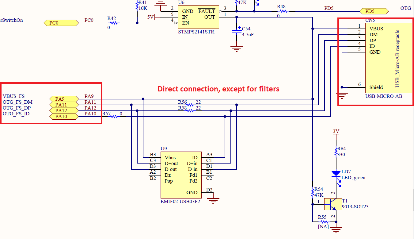
The USB schematics for STM32 are pretty straightforward. There are two 22 ohm series termination resistors that need to be placed close to the STM32 USB pins.
Everything else is optional. You can skip the USB OTG power switch in USB device designs. However, make sure VBUS is connected is VBUS detection is turned on!
If it was a hardware issue, you might have caught up with it by now.
Solution 2: Check the STM32 Clock Configuration
The clock source is very important with USB communication. The USB host will reject any USB device that has an erratic clock running its USB peripheral. We have seen this happen a lot with cheap chinese USB-UART bridge ICs with terrible resonators!
- Ensure that the STM32 is using the HSE crystal as the primary clock source.
- Double check to ensure that the crystal is actually active. You can prove the OSC_OUT pin to ensure this if you suspect a bad crystal.
- Make sure your program has the correct crystal oscillator frequency set! If you copied an STM32 USB example off the internet, this might be the problem.
Here is a reference from STM32CubeMX clock configuration utility for you to refer to. We know that this configuration works with a 8 MHz crystal!
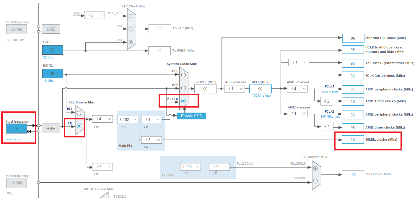
In the RCC block configuration, make sure that the HSE source is properly selected.

Solution 3: Ensure that MX_USB_DEVICE_Init() is Called
Inside the file usb_device.c, you will find a function called MX_USB_DEVICE_Init() if you generated your code using the STM32CubeMX utility.
Make sure that this function is called and the function calls within it are completely successfully.
You can check this using the SWD interface of custom hardware or STM32 Discovery board.
Solution 4: Are USB Interrupts Enabled?
If USB interrupts are disabled, the STM32Cube USB device driver will not be able to respond to requests from the USB host.
While STM32CubeMX forces you to keep updates enabled for the USB block when you use that tool to generate startup code, you can still disable global interrupts in your code.
If your application disables interrupts, make sure you either leave the USB interrupts on or re-enable them as soon as possible!
Please fill in the Quick Contact form in the sidebar if you did something else that fixed the problem!
Change Log
- Initial Release: 19 June 2021
References
- Reference 1: STM32Cube USB Device Library Documentation
11 comments
Hi, Tried all the solutions still having issues. When I setup USB class as virtual comm port it works but my USB DFU class doesnt detect. Debugging with SWD MX_USB_DEVICE_Init() gives good returns (all the functions within too). Do you have any other solutions or ideas where I can look into ?
Other than the ones listed in this article, I haven’t had anything else come up before.
You can try some USB debugging tool such as Device Monitoring Studio (https://www.hhdsoftware.com/device-monitoring-studio) to get a clear idea of what is going on.
Also, make sure Vbus detection is good and the USB device APIs aren’t being called too soon.
If your hardware is a custom STM32 board, make sure your Vbus capacitance is lower than 4.7uF (or some USB hosts will think the inrush current is a short circuit and disconnect the STM32).
Please let me know if you could figure out the problem!
Thank you! this solved my problem:
Check the crystal value. It should be 8 MHz, 12 MHz, or anything that can produce 48 MHz USB clock accurately.
Glad this helped! Make sure you use a 50 ppm crystal or better. I have seen temperature related instability with inferior crystals.
Hello, very useful guide! :) I am a pretty novice PCB designer, so forgive me if I lack the troubleshooting skills. That said, I have made a batch of USB device PCBs, using STM32 F072 as the MCU. F072 is advertised to be capable of crystal-less USB 2.0, so I did not put any external oscillators in the design. Around 20-30% of the PCBs would have the problem you described in the beginning of your article, and there are be 2 odd things that happens:
1. After cleaning the MCU and USB port pins’ contacts with the pads (using flux, rework gun, and flux cleaner), the problem goes away temporarily after re-plugging the USB. However, after 1-10 minutes, the computer can’t recognize the device again, even if I unplug and re-plug the device – that is, until I try to clean the contacts again.
2. The problematic PCB would not have the same problem when I connect it to my main computer, but the problem persists on the (multiple) target computers.
Do you think this is a design problem, or is it a Windows problem? Any pointers would be appreciated! But otherwise, great article and this guide will be very helpful for my next projects :D
Hi Milton,
Glad you found this article useful! I think that your observation with the cleaned pads might come from the fact that the STM32 part is thermally shocked when you rework the pins and that somehow affects the internal oscillator?
I know ST advertizes some parts to have crystal-less USB, but I think it is best to just use one in your USB designs. Especially those that can operate across wide temperature range and USB is important for functioning.
Another problem I would suspect is a ground loop of some sort, especially if you have the board connected to a debugger. You should only be powering the board from host PC USB. USB PC ground should be the only PCB ground. If there is another programmer connected via another USB port, that can cause problems.
Thank You, Solved with your help after reconfiguring clock. Problem with the USB clock. it was higher than 48MHz.
Thanks you again and again!
The USB interrupts got me in CubeMX on the STM32G0…
This was awesome, thank you!
We’re running a custom board with an STM32H7, and found one other thing that may trip people up.
After setting clock and pins, we had to make an invocation to HAL_PWREx_EnableUSBVoltageDetector to get things running. We cargo carried this over from https://community.st.com/s/question/0D50X00009XkX66SAF/stm32h743-nucleo-wont-work-in-usb-otg-fs.
Hope that helps some folks.
This issue is probably specific to USB OTG applications and not USB device-only configuration I guess? Because the STM32 USB peripheral will need a way to figure out whether it is in master or slave mode before it gets enumerated to a host.
When using my board self powered. My problem was solved by disabling the LSE and RTC. The LSE had a long start up time and caused the usb initialization delay longer then the computer wants to see.