The PCB Artists ESP32 4G Gateway hardware series combines and integrates a lot of features within a densely laid out PCB. In this hardware guide for Gen.1 gateways, all connectivity features are listed, along with their specifications and information on how to use them in your application.
To purchase a PCB Artists ESP32 4G Gateway Gen.1, please refer to this link:
Getting Started and Basic Setup
To get started, you will need the following items that are already included when you buy a Gateway from us:
- The ESP32 Gateway PCB
- SMA LTE antenna for cellular networking
- u.FL/IPEX antenna for Wi-Fi/BT
- ESP32 programmer
- u.FL/IPEX GPS antenna
- An external power supply (preferably 12V)
Note: Power supply is not included
- Plug in the LTE antenna to the cellular SMA antenna connector
- Plug in the Wi-Fi/BT antenna to the ESP32 WROOM module
- Insert a nano SIM card
- Plug in the ESP32 programmer to the JST connector on the Gateway
Options for powering up the Gateway are listed below.
Powering Up the Gateway
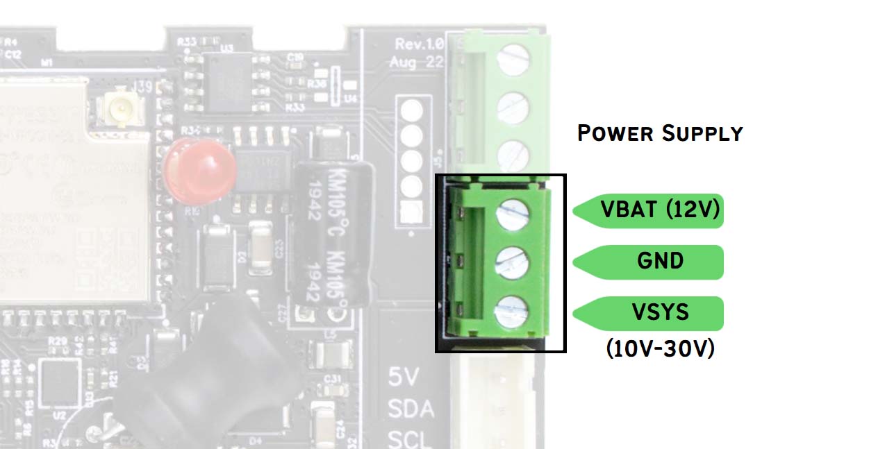
The ESP32 Gateway can be powered by either one or a combination of the following power sources:
- Regular DC power supply in the 10V-30V range (connected to VSYS and GND)
- A lead acid battery (connected to VBAT and GND)
- Power over ethernet (passive PoE of 12V/24V supplied through ethernet jack)
Using DC Power (VSYS) or Solar Power
If you have access to a standard 12V or 24V DC power supply, you may connect it to VSYS and GND to power up the gateway device. The power source connected to VSYS must be capable of supplying at least 1A of current.
If a solar panel is used, the solar panel must be connected to VSYS and GND. A lead acid battery also needs to be connected to VBAT and GND. The Gateway cannot operate with just a solar panel – a battery is mandatory for stable operation.
Note that solar panel open circuit voltage must not exceed 32V under any circumstances.
Reversing VSYS and GND polarity will damage the gateway.
Using a Lead Acid Battery (VBAT)
The gateway can be powered by a standard 12V SLA or lead acid battery. The gateway contains a built-in battery management circuit that will charge and top up the lead acid battery as required. The float voltage of the lead acid battery is maintained at 13.6V and charging terminates and restarts automatically.
Note that the lead acid battery is charged via power drawn from VSYS source. VSYS may connect to a solar panel or a regular DC power source – but charging of the battery requires the VSYS to have a voltage above 15V.
The VBAT pin has a resettable PTC fuse (2 amperes). Therefore, the PTC fuse adds a layer of safety and prevents unusual charge/discharge current when a battery is connected.
Reversing VBAT and GND polarity will damage the gateway.
Using Passive Power-over-Ethernet (PoE)
The Gateway can be powered by a passive PoE power source of 12V or 24V. A passive power injector capable of supplying 12 watts or higher should be sufficient for the gateway.
Note that PoE power cannot be used to charge a battery connected to VBAT. PoE is only used to power up the Gateway.
Combining Multiple Power Sources
You may connect several of the above mentioned power sources in any combination. When multiple power sources are connected to the Gateway, the following logic is used to determine power consumption from each power source:
- If VSYS and VBAT are both present, and VSYS is higher than 15V, then VSYS is used to charge/maintain the battery and also for gateway operation.
- When VSYS, PoE, and VBAT are all present, the source with highest voltage powers the gateway.
However, VBAT is only charged from VSYS. - VBAT is always treated as backup – if any other source is present and has a higher voltage than VBAT, that source is used to power the Gateway.
Some recommended power arrangements are listed below:
- 24V VSYS, 12V VBAT
- 24V/12V PoE, 24V VSYS, 12V VBAT
- 24V/12V PoE, 24V/12V VSYS
- 12V VBAT only
ESP32-WROOM-32UE-N8 Module
At the core of this 4G gateway design is an ESP32 module with access to all peripherals. The module we picked for the Gen.1 gateway is a WROOM-32U with u.FL antenna connector that lets you attach an external Wi-Fi antenna of your choice, this allowing you to extend and place the antenna outside a custom enclosure if needed.
Power Scheme
The ESP32 module is always powered by a 3.3V rail using any possible power source for the gateway.
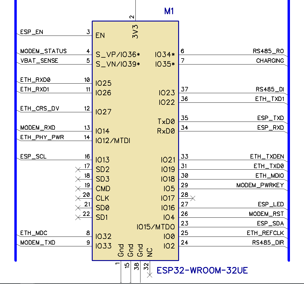
ESP32 GPIO Connections
The GPIO utilization of the ESP32 is summarized in the following quick-reference graphic. The role of each GPIO and their functions are documented in further detail later in this guide.
SIM7600 Modem
The Gateway contains a SIM7600 series modem for communication over a cellular network. You can find specifications and technical documentation for SIM7600 on the Simcom website.
The ESP32 Gateway ships with one of the following 5 modem configurations:
- SIM7600E
- SIM7600EI (India)
- SIM7600A
- SIM7600SA
- No modem
Power Scheme
The SIM7600 modem on board is powered by a buck converter that can pull power from any operating power source available to the Gateway. The available power is then regulated down to 4V for the modem to use.
When power is first fed to the Gateway, the modem powers up by default and goes to idle mode after connecting to a network (if it can). If you do not need the modem immediately, please make sure that ESP32 turns it off via the modem powerkey signal.
ESP32 GPIO Connections
The ESP32 GPIOs used for connecting to the SIM7600 modem are listed below.
- MODEM_PWRKEY to GPIO 5
Powerkey signal is connected through an inverting buffer, i.e. if GPIO 5 is high, modem powerkey pin will go low. - MODEM_RESET to GPIO 4
Reset signal is connected through an inverting buffer, i.e. if GPIO 4 is high, modem reset pin will go low. - MODEM_STATUS to GPIO 36
Direct connection via a level translator - MODEM_TXD to GPIO 33
Direct connection via a level translator - MODEM_RXD to GPIO 14
Direct connection via a level translator
Physical Connections
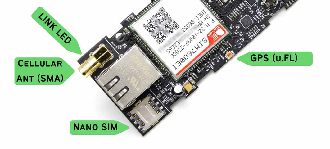
The SIM7600 modem on board connects to the following physical connectors and indicators on board:
- NanoSIM connector (push-in/pull-out type)
- SMA connector for cellular antenna
- u.FL connector for active GPS antenna
- Link indicator LED (placed under the SMA)
LAN8720 Ethernet PHY
The Gateway achieves ethernet connectivity using LAN8720 connected to the ESP32 internal RMII ethernet interface.
LAN8720 requires a 50 MHz clock to function. This clock is produced by a dedicated CMOS oscillator that can be powered on or off. The clock is turned off by default on power-up to avoid interference with ESP32 boot mode selection that depends on GPIO 0 state during power-up.
Power Scheme
The LAN8720 is powered by the same buck converter that is used to power the ESP32. It can pull power from any operating power source available to the Gateway. The available power is then regulated down to 3.3V for the LAN8720 to use.
ESP32 GPIO Connections
The ESP32 GPIOs used for connecting to the LAN8720 are listed below.
- MDIO to GPIO 18
- MDC to GPIO 32
- ETH_CLOCK_EN to GPIO 12
Setting GPIO 12 high will enable the 50 MHz ethernet clock. Please enable ethernet clock before using the LAN8720. - REFCLK_50MHZ to GPIO 0
Notes on Firmware Development
- The PHY address is set by hardware to ‘1’.
If required by menuconfig or ESP32 code, please make sure that the PHY address is set to ‘1’ or ‘scan for all addresses’. PHY address 0 will not work. - It is highly recommended that the user code turn off the ethernet clock by lowering GPIO 12 before a soft restart. GPIO 0 is a strapping pin that is shared by the clock and might prevent a proper re-boot if 50 MHz clock is enabled.
If ethernet fails to power up and work, it may be because an ESP32 programmer is connected and is driving IO 0 low/high. Please disconnect IO 0 from the programmer during ethernet debugging if ethernet initialization fails.
Physical Connections
The ethernet jack used is a standard side-insertion RJ-45 jack with yellow and green LEDs for indication.
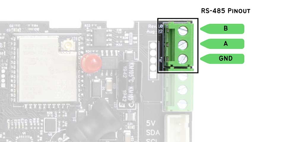
SP485E, RS485 Line Driver
RS-485 interface is enabled by SP485E on board. It can be swapped (on request) to use other interface ICs, for example, CAN bus.
Power Scheme
SP485E is powered from 5V supply derived from any usable power source available to the board.
ESP32 GPIO Connections
The ESP32 GPIOs used for connecting to the SP485E are listed below.
- DI to GPIO 23
- RO to GPIO 34
- DE/~RE to GPIO 2
DE and RE pins of the SP485E are tied together and pulled down by default.
Notes on Firmware Development
- If RS485 is not used by the application code, please ensure that GPIO 2 is configured as a GPIO and then puiled low to keep RS485 transmitter idle.
Physical Connections
System Status - LEDs, battery level, etc
The ESP32 on board can interact with the user using an on-board LED and also collect data on the charging status and battery voltage levels when required. System status functions listed below are supported:
- On-board LED for indication
- Battery voltage sensing
- Battery charger status indicator
ESP32 GPIO Connections
The ESP32 GPIOs used for system status functions are listed below.
- LED to GPIO 16
Pulling GPIO 16 down makes the LED turn on - Battery voltage to GPIO 39
Battery voltage is passed through a divider and RC filter for noise reduction.
V(bat) = 6.5 * V(gpio 39) - Charging status to GPIO 35
This GPIO reads ‘0’ when the battery is being charged (trickle, constant current or over charge mode).
When ‘1’, it means that the charger is not powered up, or that the battery is fully charged.
In rev.1.0 boards, the charging status function is not implemented yet and GPIO 35 state is invalid.
Notes on Firmware Development
- For accurate voltage reading, it is preferable to use maximum ADC sampling time (or lowest sample rate) to measure battery voltage level on GPIO 39.
Have Something to Say?
Feel free to ask away via the Live Chat, drop us a message using the Quick Contact form in the sidebar, or leave a comment below.
Change Log
- 5 February 2023
– Initial release