STM32 MCUs, especially the STM32F4 series have good support for driving relatively high resolution displays at high data rates. STM32 LVDS LCD displays are important in many application scenarios. Here are some cases where LVDS displays are preferred over RGB displays:
- Display is located far from the STM32 that drives it.
- Display cable is prone to external interference or must meet strict EMC requirements.
- You must connect the display using a multi-core cable.
- The display needs to be connected or disconnected using a simple low cost connector (mini HDMI, for example).
If your application requires these and you do not want to restrict yourself to STM32 MIPI DSI enabled variants only, LVDS is your best choice. Also, converting RGB to LVDS is easier than implementing a RGB to MIPI DSI converter.
LVDS Display Interface Basics
There are some basic features and specifications of LVDS interface that you need to keep in mind before using them in your application.
- LVDS interface has a “clock lane” and “data lanes”. Each lane consists of a differential pair.
- Most LVDS LCD displays will use 1 clock lane and 3 or 4 data lanes.
- A 6-bit LVDS often means the LCD will use an RGB666 arrangement, or 18-bit pixel color depth.
A 6-bit LVDS interface uses 1 clock lane and 3 data lanes. - An 8-bit LVDS display will often use an RGB888 arrangement, or 24-bit color depth.
An 8-bit LVDS interface uses 1 clock lane and 4 data lanes.
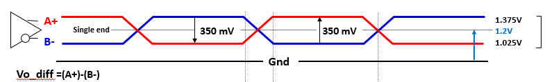
Another very important difference is that LVDS logic levels are not like the typical digital CMOS or TTL logic levels.
LVDS signals will always have a common mode voltage that is required to maintain high noise immunity. For the 7″ PCB Artists LVDS Display panel, the V (cm) or common mode voltage of the LVDS interface is 0.6V to 1.2V. A logic 0 or 1 means the voltage drops or rises differentially on that lane.
Shown below is an example of the LVDS logic levels from a Thine article on LVDS SerDes basics.
An Example of STM32 LVDS Compatible Display
LVDS displays can vary a lot. LVDS displays are not governed by a set of well defined rules like MIPI DSI displays are. Therefore, it is up to the LCD manufacturer and the LVDS display driver IC manufacturer to use LVDS interface as they please, as long as they follow the physical interface and logic levels.
For this example, our 7″ display here has
- 1024 x 600 resolution with capacitive touch
- 6-bit LVDS interface with 1 clock lane and 3 data lanes.
- RGB666 data format
- 1.2V recommended V(cm)
Based on this data, we can pick an LVDS transmitter IC. SN75LVDS84 from Texas Instruments is great for use with LCD displays that can be driven by an STM32.
LVDS Display Data Format
The format of data accepted by the LVDS LCD display controller is important. This will determine how the LVDS transmitter IC is configured and connected to the STM32 LTDC host parallel RGB output.
Here is the format of the data accepted by our LCD module, for example.
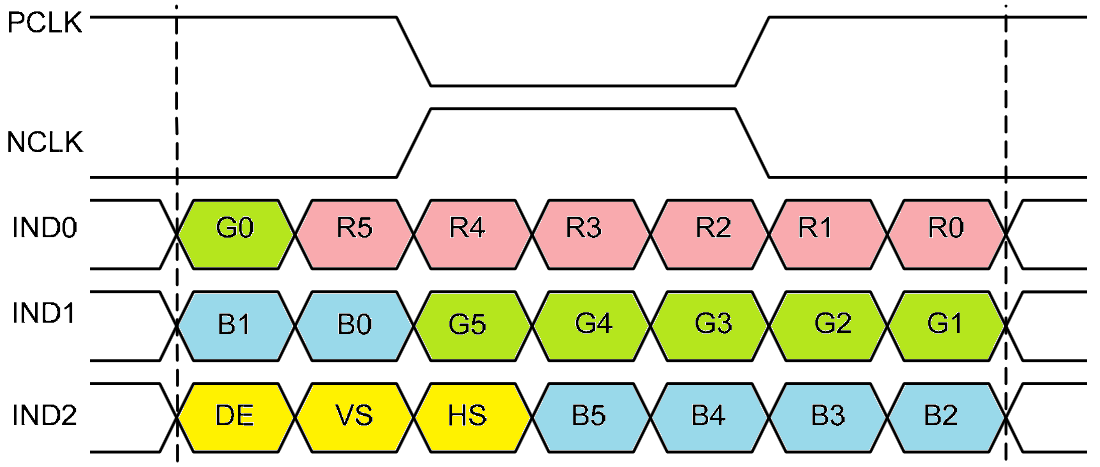
The LVDS frame packs the following signals:
- Red, R[5] to R[0]
- Green, G[5] to G[0]
- Blue, B[5] to B[0]
- Vsync, Hsync and DE strobes
LVDS Transmitted Data Format
Now that you know the input data format for the LVDS display, you need to ensure next that the parallel RGB display output from the STM32 is properly serialized to produce LVDS signals.
For this, you can take a look at your serializer or LVDS transmitter IC datasheet and how it places parallel data inputs in the LVDS frame.
For the TI SN75LVDS84, the LVDS frame produced is as shown below.
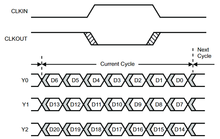
In the figure above, the bits D[20] through D[0] represent the parallel data input bus of the SN75LVDS84 LVDS transmitter IC.
Resulting STM32 LVDS LCD Transmitter Schematic
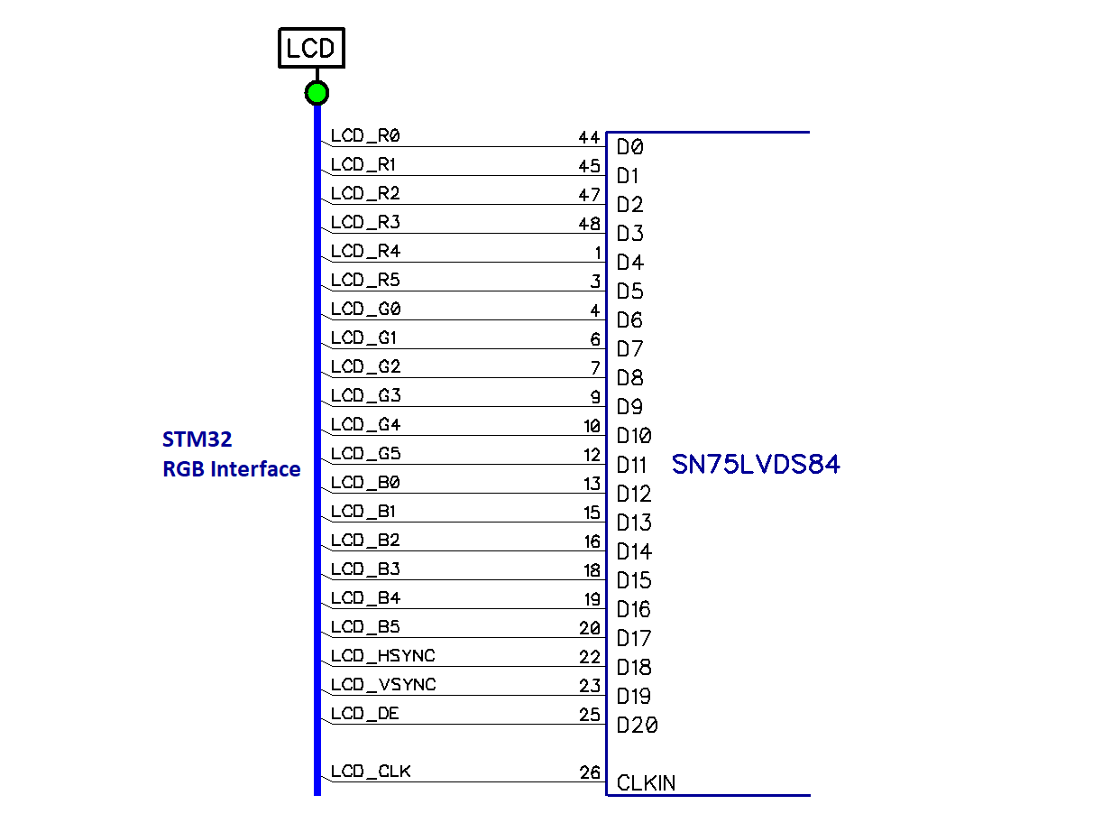
You can clearly correlate the above two diagrams to figure out which STM32 LTDC RGB signals should be routed to which LVDS transmitter pin.
Here are the resulting STM32 and SN75LVDS84 connections needed to produce the correct LVDS frame.
Some Important Notes
Here are some important notes to consider when designing STM32 systems with LVDS displays:
- Just because you can wire a display with the STM32 via LVDS does not mean you can drive them! For example, it may not be possible to drive an 1920×1080 display with an STM32 even though it has an LVDS display interface.
- With some LVDS display panels, especially those meant for use with laptops or tablets, there is a fixed frame rate that you MUST meet to drive them without flicker.
- The STM32 RGB output is usually not a bottleneck in STM32 GUI applications. The fact that the image has to be pulled constantly via DMA from the SDRAM is the bottleneck. High output frame rate can keep the STM32 internal buses busy and slow down other DMA transfers that share the same resources.
- Many LVDS displays will have no framebuffer. You must drive them at a certain minimum speed to ensure flicker-free display.
For example, the PCB Artists LVDS display must have a clock input of 20 MHz or faster. This means that you must achieve a constant 20 FPS refresh rate. This is easily done by the STM32 LTDC peripheral without wasting CPU time.
Change Log
- Initial Release: 24 June 2021
References
- Reference 1: PCB Artists LVDS Display Datasheet
- Reference 2: SN75LVDS84 Datasheet
- Reference 3: STM32F4 User Manual
- Reference 4: LG LP125WH2 LVDS LCD Display Datasheet