The ESP32 Wi-Fi/BT chip from Espressif supports PSRAM as an extension of internal addressable memory space. The ESP32 PSRAM combination is definitely much slower than the internal SRAM, but it allows you a lot of heap space in firmware to store low speed data such as audio streams and data logs.
I have put together some important reference information in this design note that I often look up when designing ESP32 and PSRAM based hardware.
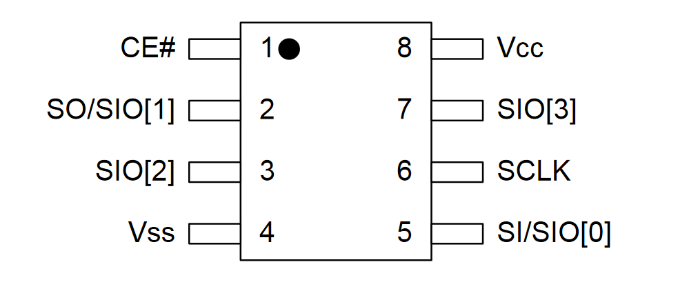
Standard PSRAM Pinout
The PSRAM chips all have a standard pinout, just like JEDEC compliant SPI flash memory chips do. Some PSRAM parts that will work with the ESP32 are:
- Espressif ESP-PSRAM32/H
- Espressif ESP-PSRAM64/H
- Ipus IPS6404
- APMemory APS6404

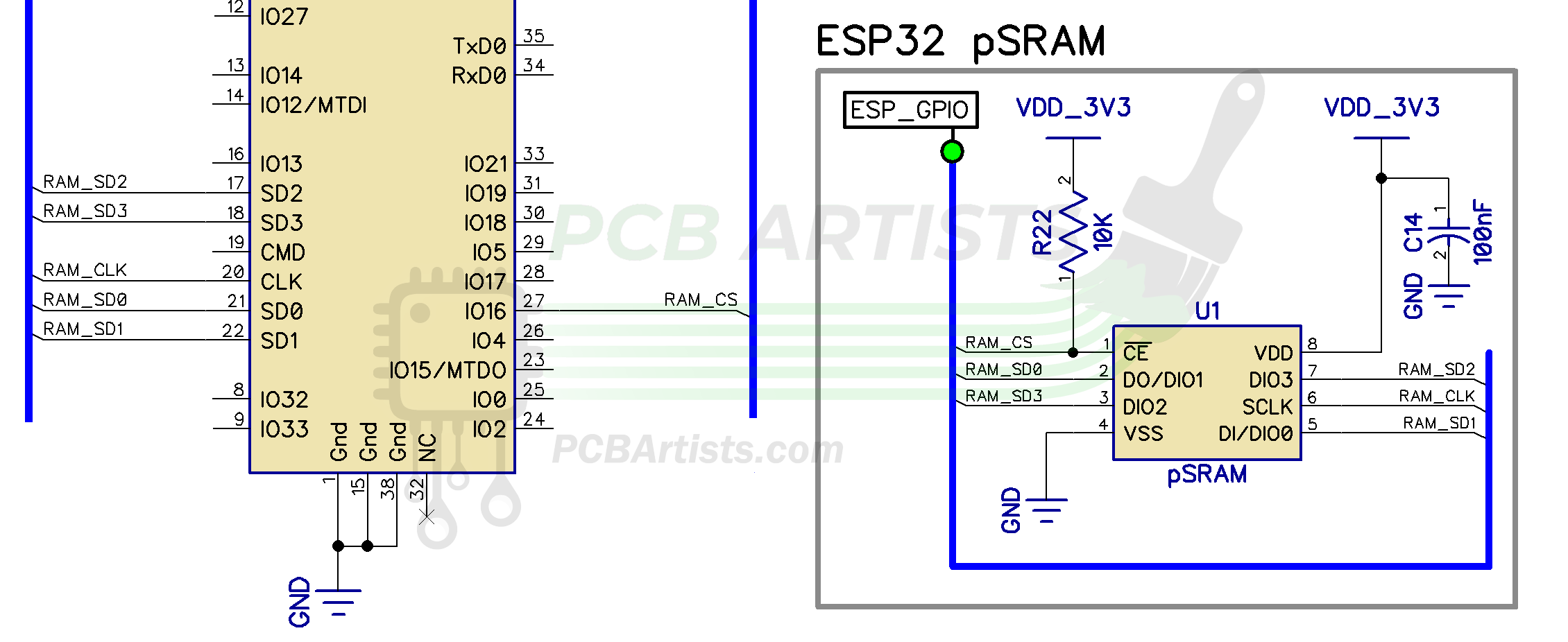
ESP32 PSRAM Schematic Example
Here is a quick schematic for interfacing PSRAM with ESP-WROOM-32D or ESP-WROOM-32U modules.
You may notice that the pinout is a little weird, for example, SD0 of ESP32 goes to DIO1 of the PSRAM. This can make the connections very confusing.
The basic idea for the PSRAM interface is that it will share data IO pins with the flash. The PSRAM will have a separate clock and chip select line.

There are some important notes that need to be taken care of when using PSRAM with the ESP32 chips. These notes are listed below.
ESP32 and PSRAM - Important Schematic and PCB Design Notes
During schematic design with ESP32 and PSRAM, you should confirm and pay attention to the following:
- Operation voltage of PSRAM
Not all PSRAM chips operate in the same voltage range. Just like SPI flash chips, PSRAM chips are available in 3.3V and 1.8V variants. The ESP32 E-fuse or boot mode selection pins (or boot strapping pins) determine the flash voltage.
Make sure you use the correct PSRAM part number for the selected voltage. Incorrect IO assignment or using a 1.8V part instead of 3.3V part can cause overcurrent or bad memory configuration boot errors. - PSRAM Clock and Chip Select Lines
Clock and CS pins can be selected by menuconfig settings. But there is a catch!
If you are using 1.8V flash, you are forced to use 1.8V PSRAM chip as well because it shares flash data IOs. This also means that the CS and CLK lines for the PSRAM must be in the 1.8V power domain. Therefore, it is important to make sure that you stick to SDIO power domain GPIOs with 1.8V PSRAM chips.
For 3.3V PSRAM, you are free to use any GPIOs as CLK and CS. - PSRAM Power Domain
ESP32 SDIO voltage can be 1.8V or 3.3V as mentioned above. In some cases, such as with ESP-WROOM-32 modules, the VDD_SDIO output of ESP32 is not available and is fixed to 3.3V. Therefore, PSRAM should be powered by 3.3V. - PSRAM power consumption in deep sleep
When powered by a fixed voltage rail and not the VDD_SDIO output, the ESP32 cannot switch the PSRAM power off when it enters deep sleep. This can cause higher deep sleep power consumption. A work-around could be to use a GPIO with RC-delay to turn the PSRAM off just before entering deep sleep mode.
As for PCB design, things that matter are:
- The clock trace should be the longest trace of all the SPI bus lines connecting ESP32 and the PSRAM chip.
- It is a good idea to have a series termination resistor footprint on the clock line. You can use 0R or 33R by default, or a higher value to adjust the bus timing if needed.
- Ensure solid ground plane under the SPI bus lines. PSRAM is a high speed device and vulnerable to noise and data corruption if you don’t route the PCB properly.
ESP32-PICO-D4 and PSRAM
The PICO-D4 provides VDD_SDIO output. The above schematic will still be valid – however, you should power the PSRAM chip using the VDD_SDIO output of the ESP32.
The PICO-D4 chip uses a 3.3V flash internally. Therefore, you should use a 3.3V PSRAM with the PICO-D4.
Have Something to Say?
Feel free to ask away via the Live Chat, drop us a message using the Quick Contact form in the sidebar, or leave a comment below.
Change Log
- 13 August 2021
– Initial release - 14 February 2023
– Added notes on PSRAM CLK and CS pin configuration
References
- Reference 1: Ipus IPS6404 Datasheet
- Reference 2: Espressif ESP-PSRAM64 Datasheet
- Reference 3: ESP-WROOM-32 Datasheet
1 comment
You are a lifesaver!