Some STM32 series of MCUs have a DCMI peripheral that can be used to interface the STM32 chip directly tocamera sensors. The DCMI is flexible enough to support a variety of sensors that output data using a parallel data interface (RGB).
To demonstrate the DCMI camera interface capabilities, we will make use of a simple STM32 OV2640 camera interfacing example.
Determining the camera connections
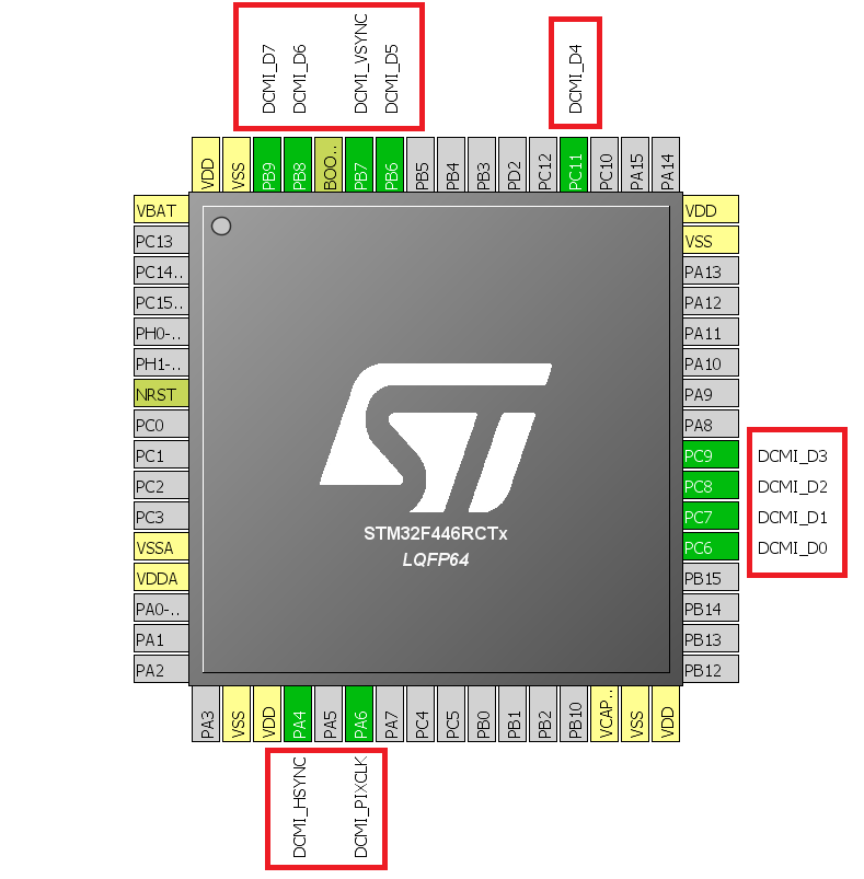
The STM32 does not have a GPIO matrix, which means that you cannot assign any internal peripheral function to any GPIO as you wish to. You must use certain physical pins for their DCMI related functions. Most DCMI pins such as data lines have an alternate pin available.
You can find out the required DCMI pins from the STM32 part datasheet. However, we feel it is much easier and safer to just use STM32 CubeMX GUI application. It allows you to simply select the pins using a GUI. This leaves no opportunity for error if you are designing a PCB and a mistake can prove to be expensive.
In this article, we take the STM32F446 as an example. It is one of the lowest cost STM32 variants that sport the DCMI peripheral.
Camera signals and what they do
Certain signal lines are crucial to get the data out from the camera sensor properly. Here are the signal lines, described in short. Note that there may be additional signal lines needed, other than the DCMI (image data bus).
- PCLK: PCLK or PIXCLK is the pixel clock. Data for each pixel can be read out on the rising or falling edge of the PCLK signal. This is usually the highest frequency signal line in the interface. With the STM32, PCLK can reach up to 50 MHz.
- VSYNC: Vertical sync signal can be considered to be equivalent to the vertical blanking signal. It marks the end of a “frame” in the data stream. In other words, the VSYNC is pulsed every time a frame ends. If the camera output was set to 15 fps, VSYNC will measure 15 Hz.
- HSYNC: Horizontal sync signal can be considered to be equivalent to the horizontal blanking signal. It marks the end of a “line” in the data stream. In other words, the HSYNC is pulsed every time a line ends. If the camera output was set to 15 fps, 240×160 resolution, HSYNC will measure 15×240 lines =3600 Hz.
- DATA: The data lines simply latch valid data during the specified PCLK edge. Most camera sensors allow configuration of the VSYNC, HSYNC and PCLK polarity.
Additional camera interface signals
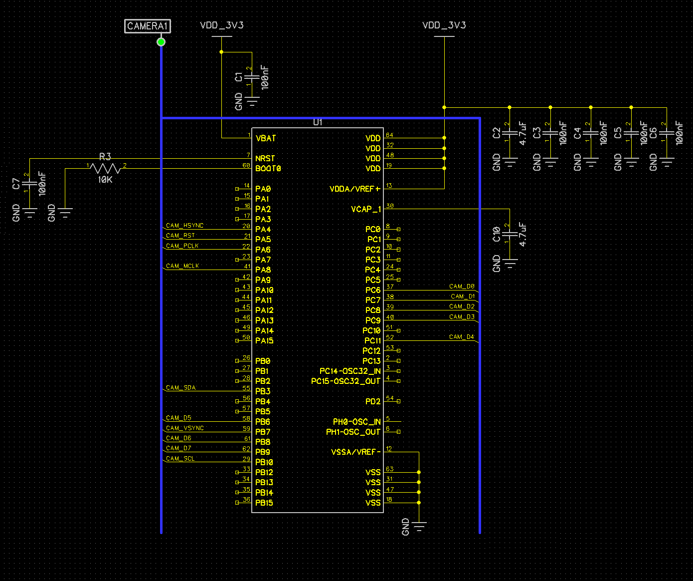
STM32 OV2640 camera interfacing
Here is how a typical STM32 OV2640 interface looks like at the circuit level.
References
Reference 1: OV2640 Datasheet