Here is a complete and detailed guide to all I2C registers and their respective functions available on our new Advanced I2C Sound Level Sensor module.
Each register description block below contains a bit-wise function description and power-on/reset default values. For programming examples and detailed explanation of the parameters measured and how they are calculated, please refer to the product page.
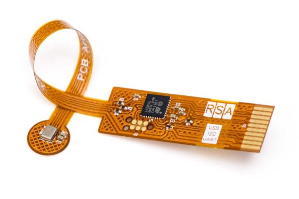
Applicable Products
This documentation applies to the following product(s) only:
- Advanced I2C Sound Level Sensor – Product Link
Sound Level Sensor Programming Basics
The Advanced Sound Level Sensor is equipped with a standard I2C interface for communication with the host MCU. No specific initialization sequence is necessary and the module powers up with a commonly used combination of settings:
- A-weighting, C-weighting, and Z-weighting are enabled simultaneously
- 1000 ms time-weighting duration (“slow mode” on commercial sound meters)
- Interrupt function is disabled
- It is recommended to reset all history, min/max and peak values 50ms after the module is powered up or reset. This helps clear up any power-on “pop” related inaccurate values.
I2C Interface and Communication
Communicating with the Decibel Meter Module
The PCB Artists sound level meter is ready for communication over I2C within 5 ms of power-up or reset.
The host can communicate with the module by accessing the 7-bit device I2C address (0x48 by default, unless you ordered a custom module).
The host can then read any register any time for reading the latest sound level data. However, if some parameters have not been calculated yet, they will read 0. A 0-value in any sound level data register means that the value is invalid and has not yet been calculated. A host should ignore such values.
Naming convention used for this section to describe I2C operations are:
DEV_ADDR – I2C device address
REG_ADDR – Device register address to read from or write to
R/W Read/write bit in the I2C device address frame
ACK – Acknowledge condition on the I2C bus
NACK – No-acknowledge condition on the I2C bus
START – Start condition on the I2C bus
STOP – Stop condition on the I2C bus
RESTART – Re-start or (stop + start) condition on the I2C bus
I2C Single Byte Write Sequence
- Generate a START condition
- Send DEV_ADDR with R/W bit set to ‘0’ (write)
- Send REG_ADDR
- Send the data byte to be written at REG_ADDR
- Generate a STOP condition
I2C Single Byte Read Sequence
- Generate a START condition
- Send DEV_ADDR with R/W bit set to ‘0’ (write)
- Send REG_ADDR
- Generate a RESTART condition
- Send DEV_ADDR with R/W bit set to ‘1’ (read)
- Read data from REG_ADDR
- Generate a STOP condition
I2C Multi-Byte Write Sequence
- Generate a START condition
- Send DEV_ADDR with R/W bit set to ‘0’ (write)
- Send REG_ADDR
- Send consecutive data bytes to be written starting at REG_ADDR
- Generate a STOP condition
I2C Multi-Byte Read Sequence
- Generate a START condition
- Send DEV_ADDR with R/W bit set to ‘0’ (write)
- Send REG_ADDR
- Generate a RESTART condition
- Send DEV_ADDR with R/W bit set to ‘1’ (read)
- Read consecutive data bytes starting at REG_ADDR
- Generate a STOP condition
I2C Sound Level Sensor Register Map
The PCB Artists Advanced I2C sound level sensor implements the following registers. The host should not try to read from or write to undocumented locations as they are reserved for diagnostics, calibration and future use.
VERSION - Register 0
| ADDRESS | DEFAULT VALUE | TYPE |
| 0x00 | See section “version notes” | R/O |
DESCRIPTION
- BIT [7:4] – HW Version
Hardware version - BIT [3:0] – FW Version
Firmware version
ID3:ID2:ID1:ID0 - Registers 1, 2, 3, and 4
| ADDRESS | DEFAULT VALUE | TYPE |
| 0x01 – 0x04 | 32-bit Unique ID | R/O |
DESCRIPTION
- BIT [31:0] – Device ID
32-bit unique device ID (4 bytes)
RESERVED - Register 5
| ADDRESS | DEFAULT VALUE | TYPE |
| 0x05 | – | R/W |
DESCRIPTION
- BIT [7:0] – Reserved
Reserved register, do not write anything to this register.
Value read from this register is not defined.
CONTROL - Register 6
| ADDRESS | DEFAULT VALUE | TYPE |
| 0x06 | 0x04 | R/W |
DESCRIPTION
- BIT [7:3] – Reserved
Do not write 1 to these bits - BIT [2] – Interrupt Type
Selects the cause of interrupt signal being asserted.
– If 1 (default), THR_MIN and THR_MAX registers are used as threshold values. When A-weighted, time-weighted decibel reading (“dBA”) falls outside the range set by THR_MIN and THR_MAX, the interrupt pin is activated.
– If 0, INT pin goes low when the seconds history buffer is full, i.e. every 60 seconds. - BIT [1] – Interrupt Enable
Set to enable the interrupt pin operation. INT pin goes low to indicate a pending interrupt.
A pending interrupt must be cleared by writing to the RESET register. - BIT [0] – Power Down
Set this bit to power down the sound level sensor. Writing a 0 does nothing.
NOTE: To wake up the module, the host must set bit [5] of RESET register to cause a module reset.
Failing to do so can put the module in an unknown state. After wake-up and reset, the module settings are restored to their power-up default state and application can use the module as usual.
TAVG_HIGH - Register 7
| ADDRESS | DEFAULT VALUE | TYPE |
| 0x07 | 0x03 | R/W |
DESCRIPTION
- BIT [7:0] – Tavg_high
Averaging time (high byte) in milliseconds for calculating sound intensity levels. This register, and TAVG_LOW register together form a 16-bit Tavg value.
Set [Tavg_high:Tavg_low] = 1,000 for slow mode intensity measurement.
Set [Tavg_high:Tavg_low] = 125 for fast mode intensity measurement.
TAVG_LOW - Register 8
| ADDRESS | DEFAULT VALUE | TYPE |
| 0x08 | 0xE8 | R/W |
DESCRIPTION
- BIT [7:0] – Tavg_low
Averaging time (low byte) in milliseconds for calculating sound intensity levels.
Set [Tavg_high:Tavg_low] = 1,000 for slow mode intensity measurement.
Set [Tavg_high:Tavg_low] = 125 for fast mode intensity measurement.
NOTE: Writing to Tavg_low causes the combined value of Tavg_high:Tavg_low to take effect. Therefore, Tavg_high must be written first.
As Tavg is a 16-bit value, Tavg = 256*TAVG_HIGH + TAVG_LOW
RESET - Register 9
| ADDRESS | DEFAULT VALUE | TYPE |
| 0x09 | 0x00 | W/O |
DESCRIPTION
- BIT [7:6] – Reserved
- BIT [5] – SYSTEM RESET
Set this bit to trigger a system reset. All module registers are restored to their default values as mentioned in this register map. This bit is automatically cleared.
NOTE: This bit must be set to wake up the device from sleep mode. - BIT [4] – Reset Peak
Set this bit to clear the peak values stored in LApk, LCpk, and LZpk. This bit is automatically cleared. - BIT [3] – Reset Time Over/Under Count
Set this bit to clear the count of seconds-over-threshold and seconds-under-threshold counter. This bit is automatically cleared. - BIT [2] – Reset History
Set this bit to clear the LAeq history buffer data, which includes the seconds-history, minutes-history, and hours-history registers. This bit is self-clearing. - BIT [1] – Reset MIN/MAX
Set this bit to clear the LAmax, LCmax, LZmax, LAmin, LCmin, and LZmin values. This bit is self-clearing. - BIT [0] – Reset Interrupt
Set this bit to clear interrupt signal and set INT pin to high-Z. This bit is self-clearing.
dBA, Integer and Decimal - Registers 10 and 11
| ADDRESS | DEFAULT VALUE | TYPE |
| 0x0A | 0x00 | R/O |
| 0x0B | 0x00 | R/O |
DESCRIPTION
- Register 10 (0x0A) – Integer Part of dBA
- Register 11 (0x0B) – Decimal Part of dBA
dBA is the A-weighted, time-weighted sound level using Tavg value for time weighting.
dBC, Integer and Decimal - Registers 12 and 13
| ADDRESS | DEFAULT VALUE | TYPE |
| 0x0C | 0x00 | R/O |
| 0x0D | 0x00 | R/O |
DESCRIPTION
- Register 12 (0x0C) – Integer Part of dBC
- Register 13 (0x0D) – Decimal Part of dBC
dBC is the C-weighted, time-weighted sound level using Tavg value for time weighting.
dBZ, Integer and Decimal - Registers 14 and 15
| ADDRESS | DEFAULT VALUE | TYPE |
| 0x0E | 0x00 | R/O |
| 0x0F | 0x00 | R/O |
DESCRIPTION
- Register 14 (0x0E) – Integer Part of dBZ
- Register 15 (0x0F) – Decimal Part of dBZ
dBZ is the Z-weighted, time-weighted sound level using Tavg value for time weighting.
LAeq(fast), Integer and Decimal - Registers 16 and 17
| ADDRESS | DEFAULT VALUE | TYPE |
| 0x10 | 0x00 | R/O |
| 0x11 | 0x00 | R/O |
DESCRIPTION
- Register 16 (0x10) – Integer Part of LAeq,fast
- Register 17 (0x11) – Decimal Part of LAeq,fast
LAeq,fast is the A-weighted, equivalent continuous sound level measured over 250ms.
LCeq(fast), Integer and Decimal - Registers 18 and 19
| ADDRESS | DEFAULT VALUE | TYPE |
| 0x12 | 0x00 | R/O |
| 0x13 | 0x00 | R/O |
DESCRIPTION
- Register 18 (0x12) – Integer Part of LCeq,fast
- Register 19 (0x13) – Decimal Part of LCeq,fast
LCeq,fast is the C-weighted, equivalent continuous sound level measured over 250ms.
LZeq(fast), Integer and Decimal - Registers 20 and 21
| ADDRESS | DEFAULT VALUE | TYPE |
| 0x14 | 0x00 | R/O |
| 0x15 | 0x00 | R/O |
DESCRIPTION
- Register 20 (0x14) – Integer Part of LZeq,fast
- Register 21 (0x15) – Decimal Part of LZeq,fast
LZeq,fast is the Z-weighted, equivalent continuous sound level measured over 250ms.
LAeq(slow), Integer and Decimal - Registers 22 and 23
| ADDRESS | DEFAULT VALUE | TYPE |
| 0x16 | 0x00 | R/O |
| 0x17 | 0x00 | R/O |
DESCRIPTION
- Register 22 (0x16) – Integer Part of LAeq,slow
- Register 23 (0x17) – Decimal Part of LAeq,slow
LAeq,slow is the A-weighted, equivalent continuous sound level measured over 1 second.
LCeq(slow), Integer and Decimal - Registers 24 and 25
| ADDRESS | DEFAULT VALUE | TYPE |
| 0x18 | 0x00 | R/O |
| 0x19 | 0x00 | R/O |
DESCRIPTION
- Register 24 (0x18) – Integer Part of LCeq,slow
- Register 25 (0x19) – Decimal Part of LCeq,slow
LCeq,slow is the C-weighted, equivalent continuous sound level measured over 1 second.
LZeq(slow), Integer and Decimal - Registers 26 and 27
| ADDRESS | DEFAULT VALUE | TYPE |
| 0x1A | 0x00 | R/O |
| 0x1B | 0x00 | R/O |
DESCRIPTION
- Register 26 (0x1A) – Integer Part of LZeq,slow
- Register 27 (0x1B) – Decimal Part of LZeq,slow
LZeq,slow is the Z-weighted, equivalent continuous sound level measured over 1 second.
LApeak, Integer and Decimal - Registers 28 and 29
| ADDRESS | DEFAULT VALUE | TYPE |
| 0x1C | 0x00 | R/O |
| 0x1D | 0x00 | R/O |
DESCRIPTION
- Register 28 (0x1C) – Integer Part of LApeak
- Register 29 (0x1D) – Decimal Part of LApeak
LApeak is the A-weighted peak sound pressure level. The peak value is the highest observed peak since the last peak reset operation.
LCpeak, Integer and Decimal - Registers 30 and 31
| ADDRESS | DEFAULT VALUE | TYPE |
| 0x1E | 0x00 | R/O |
| 0x1F | 0x00 | R/O |
DESCRIPTION
- Register 30 (0x1E) – Integer Part of LCpeak
- Register 31 (0x1F) – Decimal Part of LCpeak
LCpeak is the C-weighted peak sound pressure level. The peak value is the highest observed peak since the last peak reset operation.
LZpeak, Integer and Decimal - Registers 32 and 33
| ADDRESS | DEFAULT VALUE | TYPE |
| 0x20 | 0x00 | R/O |
| 0x21 | 0x00 | R/O |
DESCRIPTION
- Register 32 (0x20) – Integer Part of LZpeak
- Register 33 (0x21) – Decimal Part of LZpeak
LZpeak is the Z-weighted peak sound pressure level. The peak value is the highest observed peak since the last peak reset operation.
LAmax, Integer and Decimal - Registers 34 and 35
| ADDRESS | DEFAULT VALUE | TYPE |
| 0x22 | 0x00 | R/O |
| 0x23 | 0x00 | R/O |
DESCRIPTION
- Register 34 (0x22) – Integer Part of LAmax
- Register 35 (0x23) – Decimal Part of LAmax
LAmax is the maximum dBA value (time-weighted over Tavg) observed since the last max/min reset operation.
LCmax, Integer and Decimal - Registers 36 and 37
| ADDRESS | DEFAULT VALUE | TYPE |
| 0x24 | 0x00 | R/O |
| 0x25 | 0x00 | R/O |
DESCRIPTION
- Register 36 (0x24) – Integer Part of LCmax
- Register 37 (0x25) – Decimal Part of LCmax
LCmax is the maximum dBC value (time-weighted over Tavg) observed since the last max/min reset operation.
LZmax, Integer and Decimal - Registers 38 and 39
| ADDRESS | DEFAULT VALUE | TYPE |
| 0x26 | 0x00 | R/O |
| 0x27 | 0x00 | R/O |
DESCRIPTION
- Register 38 (0x26) – Integer Part of LZmax
- Register 39 (0x27) – Decimal Part of LZmax
LZmax is the maximum dBZ value (time-weighted over Tavg) observed since the last max/min reset operation.
LAmin, Integer and Decimal - Registers 40 and 41
| ADDRESS | DEFAULT VALUE | TYPE |
| 0x28 | 0x00 | R/O |
| 0x29 | 0x00 | R/O |
DESCRIPTION
- Register 40 (0x28) – Integer Part of LAmin
- Register 41 (0x29) – Decimal Part of LAmin
LAmin is the minimum dBA value (time-weighted over Tavg) observed since the last max/min reset operation.
LCmin, Integer and Decimal - Registers 42 and 43
| ADDRESS | DEFAULT VALUE | TYPE |
| 0x2A | 0x00 | R/O |
| 0x2B | 0x00 | R/O |
DESCRIPTION
- Register 42 (0x2A) – Integer Part of LCmin
- Register 43 (0x2B) – Decimal Part of LCmin
LCmin is the minimum dBC value (time-weighted over Tavg) observed since the last max/min reset operation.
LZmin, Integer and Decimal - Registers 44 and 45
| ADDRESS | DEFAULT VALUE | TYPE |
| 0x2C | 0x00 | R/O |
| 0x2D | 0x00 | R/O |
DESCRIPTION
- Register 44 (0x2C) – Integer Part of LZmin
- Register 45 (0x2D) – Decimal Part of LZmin
LZmin is the minimum dBZ value (time-weighted over Tavg) observed since the last max/min reset operation.
THR_OVER - Register 46
| ADDRESS | DEFAULT VALUE | TYPE |
| 0x2E | 85’d | R/W |
DESCRIPTION
- BIT [7:0] – Upper sound level threshold
Threshold value in A-weighted dB SPL.
This value is used in several functions like level based interrupt and counting seconds-over value, etc.
THR_MIN - Register 47
| ADDRESS | DEFAULT VALUE | TYPE |
| 0x2F | 45’d | R/W |
DESCRIPTION
- BIT [7:0] – Lower sound level threshold
Threshold value in A-weighted dB SPL.
This value is used in several functions like level based interrupt and counting seconds-under value, etc.
SECONDS_OVER - Registers 48, 49 and 50
| ADDRESS | DEFAULT VALUE | TYPE |
| 0x30 | 0x00 | R/O |
| 0x31 | 0x00 | R/O |
| 0x32 | 0x00 | R/O |
DESCRIPTION
- Register 48 (0x30) – Byte 2 of 24-bit seconds_over value (MSB)
- Register 49 (0x31) – Byte 1 of 24-bit seconds_over value
- Register 50 (0x32) – Byte 0 of 24-bit seconds_over value (LSB)
Total number of seconds for which Leq,slow was higher than THR_MAX since the last reset operation.
SECONDS_OVER = Reg48*65536 + Reg49*256 + Reg50
SECONDS_UNDER - Registers 51, 52 and 53
| ADDRESS | DEFAULT VALUE | TYPE |
| 0x33 | 0x00 | R/O |
| 0x34 | 0x00 | R/O |
| 0x35 | 0x00 | R/O |
DESCRIPTION
- Register 51 (0x33) – Byte 2 of 24-bit seconds_under value (MSB)
- Register 52 (0x34) – Byte 1 of 24-bit seconds_under value
- Register 53 (0x35) – Byte 0 of 24-bit seconds_under value (LSB)
Total number of seconds for which Leq,slow was lower than THR_MIN since the last reset operation.
SECONDS_UNDER = Reg51*65536 + Reg52*256 + Reg53
SECONDS_HISTORY - Registers 100 to 159
| ADDRESS | DEFAULT VALUE | TYPE |
| 0x64 | 0x00 | R/O |
| … | … | … |
| 0x9F | 0x00 | R/O |
DESCRIPTION
- Register 100 (0x64) to Register 159 (0x9F) – LAeq,slow data for the last 60 seconds
Register 159 contains the oldest data. New LAeq,slow values are inserted every second at Register 100 and data is shifted back every second new data is available.
MINUTES_HISTORY - Registers 160 to 219
| ADDRESS | DEFAULT VALUE | TYPE |
| 0xA0 | 0x00 | R/O |
| … | … | … |
| 0xDB | 0x00 | R/O |
DESCRIPTION
- Register 160 (0xA0) to Register 219 (0xDB) – LAeq,1min data for the last 60 minutes
Register 219 contains the oldest data. New LAeq,1min values are inserted every minute at Register 160 and data is shifted back every minute new data is available.
Each LAeq,1min value is the LAeq value over 1 minute periods.
HOURS_HISTORY - Registers 220 to 231
| ADDRESS | DEFAULT VALUE | TYPE |
| 0xDC | 0x00 | R/O |
| … | … | … |
| 0xE7 | 0x00 | R/O |
DESCRIPTION
- Register 220 (0xDC) to Register 231 (0xE7) – LAeq,1hr data for the last 12 hours
Register 231 contains the oldest data. New LAeq,1hr values are inserted every hour at Register 220 and data is shifted back every hour new data is available.
Each LAeq,1hr value is the LAeq value over 1 hour periods.
Firmware Version Notes
Below are detailed notes on module versions, release notes and variations across versions.
VERSION = 0xA0 (long term support and available for sale)
Flexible Sensor Module v10 (SKU: PCBA-DBM-FLEX) + Firmware v0 is currently available for sale on our store and will be supported for long term use.
Any future firmware updates will retain backward compatibility with firmware v1.
Hardware v10 + Firmware v0 notes:
- Meets specifications and functions as per register descriptions above
- I2C protocol tested to work reliably with host MCUs that use Arduino Wire library
- No known bugs
Change Log
- 26 October 2024
– Initial release