
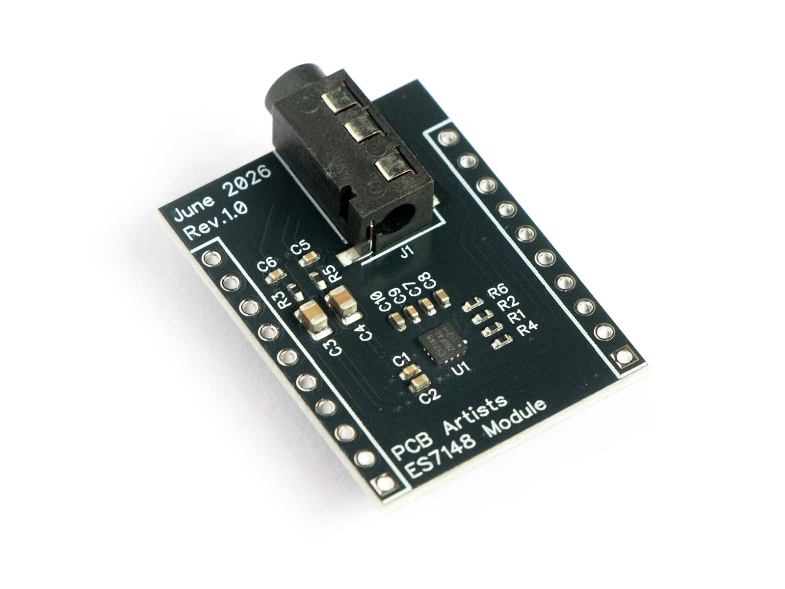
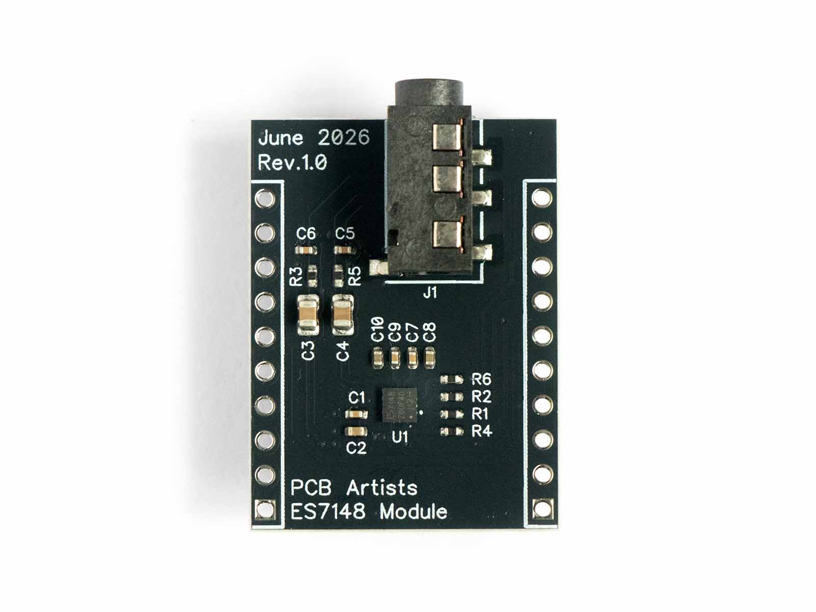
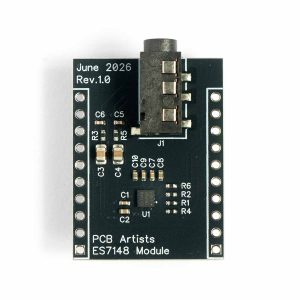
The PCB Artists ES7148 module is a stereo 24-bit DAC module that needs no configuration at all. All you need to do is power up the module, provide MCLK, send a stream of stereo I²S data and it plays crystal-clear audio.
No I²C bus, no complex codec configuration – same footprint as our ES8388 module.
No I²C required
Detects sample rate automatically
3.5 mm jack (headphone*/line-out)
Low-noise split-ground PCB layout
Overview
The ES7148 is a simple, low-cost stereo audio DAC. This module allows you to test and prototype with this audio DAC without spinning up your own custom PCB.
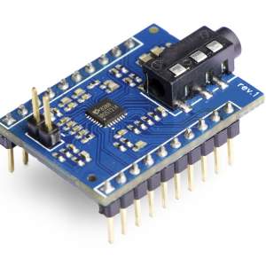
You may have already tried our other codec modules. This module follows the same pinout and form-factor so you can drop in and try the ES7148 module.
The ES7148 is quite popular and makes an appearance in boards like Espressif’s ESP32-Korvo-DU1906.
The ES7148 is quite popular and makes an appearance in boards like Espressif’s ESP32-Korvo-DU1906.
What makes the ES7148 module unique is that it is very beginner-friendly and requires no setup or configuration.
If you are at the beginning phases of making a system that needs to play back audio – this module is perfect for your project.
There are no drivers and configuration issues to troubleshoot and that helps speed up simple playback applications.
We have carefully split analog and digital ground planes for good noise immunity. The line output are available on the 3.5mm jack, as well as the 0.1″ header.
Because the output is AC coupled, you can feed the line output to any other audio equipment such as an amplifier or recorder. The low-pass filter ou the output lines suppresses whatever noise is caused by digital signal lines on a prototyping setup.
No configuration needed
- No I²C bus or control registers
- Sample rate detected automatically
- I²S word length detected automatically
- Self-resets on power-up
- Automatic soft-start audio output
Clear and quiet by design
- Split analog and digital ground planes
- 100 dB SNR, 105 dB dynamic range
- 100 dB channel separation at 1 kHz
- Low jitter sensitivity
Features
No I²C, no register writes, no codec driver to port. Bring up the I²S peripheral and you are done – typically under twenty lines of code on an ESP32!
Accepts simple clock multiples and arbitrary sample rates that most microcontrollers with an I²S interface can produce. You will not need strange clock frequencies or a dedicated crystal.
100 dB SNR, −85 dB THD+N and 105 dB dynamic range, helped along by split ground planes and local supply filtering on the module.
Same outline, same 0.1" header, same positions for power, ground and the I²S signals. You can swap between our modules without touching your layout or wiring.
ES7148 or ES8388?
All our audio modules are largely pin- and form-factor compatible to allow you to try several modules without major changes.
The ES7148 module is the shortest and easiest path to adding qualiy audio playback to your embedded system.
Pick the ES8388 module when you need to record, or when you want control over gain, mixing and ALC.
| ES7148 Module | ES8388 Module | |
|---|---|---|
| Function | DAC (playback) only | Full codec |
| Playback | ✓ | ✓ |
| Recording / mic input | — | ✓ |
| Control bus | — | I²C |
| Driver needed | None | ✓ |
| Max sample rate | 200 kHz | 96 kHz |
| Resolution | 24-bit | 24-bit |
| SNR | 100 dB (DAC) | 96 dB (DAC) |
| Digital volume / ALC | — | ✓ |
| Headphone amplifier | AC-coupled line out | Integrated driver |
| Supply current | TBD mA | 10 mA playback |
| ESP-ADF support | Not required | ✓ |
The ES7148 has no volume control register.
With 24-bit data as the full scale, you can scale down the samples in software before streaming to the I²S. Thanks to 24-bit data you have plenty of headroom to attenuate digitally.
Specifications
Audio Characteristics
| Resolution | 16 – 24 bit, detected automatically |
|---|---|
| Sample rates | 8 kHz – 200 kHz |
| Signal to noise ratio | 100 dB typical, 90 dB minimum (A-weighted) |
| THD + N | −85 dB typical, −80 dB maximum |
| Dynamic range | 105 dB typical |
| Channel separation | 100 dB typical at 1 kHz |
| Frequency response | −0.02 / +0.08 dB, 20 Hz – 20 kHz |
| Interchannel gain mismatch | 0 dB typical |
Measured at VDD = 3.3 V, 25 °C, Fs = 48 kHz,
CLKIN/LRCK = 256, 0 dB 1 kHz sine input.
Power Supply
| Supply voltage | 3.0 – 3.6 V (3.3 V typical) |
|---|---|
| Current, normal operation | 19 mA typical at 3.3 V |
| Current, power-down | 8 mA typical at 3.3 V |
| Digital I/O levels | 1.8 V or 3.3 V logic |
| Absolute maximum supply | 3.6 V — do not exceed |
Digital Interface
| Audio interface | I²S, 16 – 24 bit, slave only |
|---|---|
| Control interface | None |
| CLKIN frequency | 51.2 MHz maximum |
| SCLK frequency | 26 MHz maximum |
| LRCK frequency | 200 kHz maximum |
Analog output
| Full-scale output level | 0.7 × VDD Vpp (2.31 Vpp at 3.3 V) |
|---|---|
| Output impedance | 120 Ω (ES7148) |
| Minimum load resistance | 2 kΩ see ES7148 Datasheet |
| Maximum load capacitance | 100 pF |
| Module output coupling | 22 µF series capacitor + 33 Ω series resistor, both channels |
| Connectors | 3.5 mm stereo jack and 0.1" header pins |
Physical
| Form factor | Identical to the PCB Artists ES8388 module |
|---|---|
| Connections | 20-pin, 0.1" pitch Ships with un-soldered headers |
| SKU | ES7148-MOD |
Clocking
The clock frequency and ratio are the only configuration element that you need to deal with. The ES7148 uses CLKIN-to-LRCK ratio for its internal DAC and filters.
Pick any valid frequency and ratio from the ES7148 datasheet.
| Speed mode | Sample rate | CLKIN / LRCK ratio |
|---|---|---|
| Single | 8 – 50 kHz | 128, 256, 384, 512, 640, 768, 1024, 1152, 1280, 1536 |
| Double | 64 – 100 kHz | 64, 192 |
| Quad | 167 – 200 kHz | 32, 96 |
On supplying VDD, the device self-resets and enters power-down. It exits power-down only when valid CLKIN and LRCK are present, then ramps the outputs softly to the common-mode voltage.
Silence on power-up even with valid I²S stream usually means a missing clock (loose connections, etc.).
Pinout
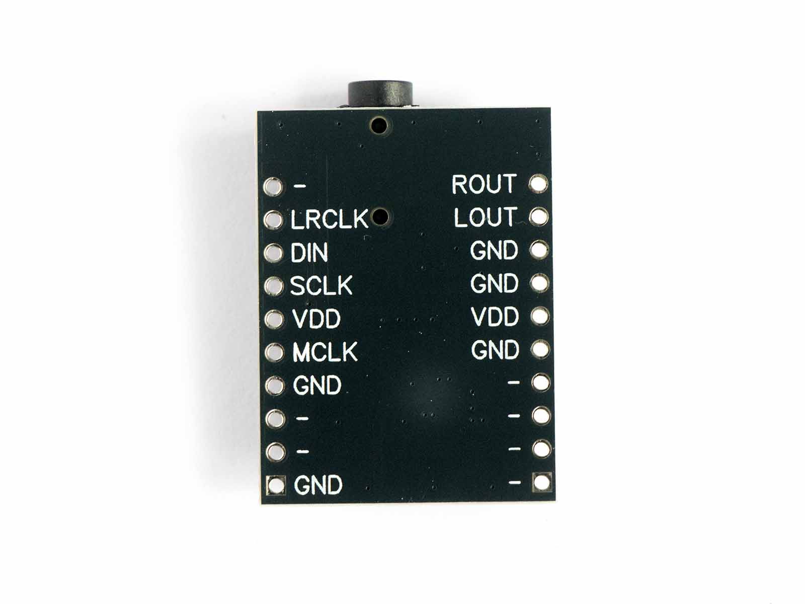
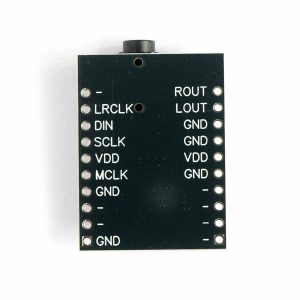
Twenty pins on a 0.1" grid, in the same positions as our ES8388 module. Because the ES7148 only outputs audio, the DOUT pin is not connected.
On the analog side, audio input lines are not connected.
VDD pins on both sides are internally connected, and GND pins are all internally connected.
We recommend connecting GND on both sides for best low-noise performance.
| # | Name | Domain | Description |
|---|---|---|---|
| Analog outputs | |||
| 1 | ROUT | AVDD | Right channel out — AC-coupled, also on the 3.5 mm jack |
| 2 | LOUT | AVDD | Left channel out — AC-coupled, also on the 3.5 mm jack |
| I²S audio bus | |||
| 15 | MCLK | DVDD | System clock in — CLKIN on the ES7148 |
| 17 | SCLK | DVDD | Bit clock in |
| 18 | DIN | DVDD | Serial audio data in — SDATA on the ES7148 |
| 19 | LRCLK | DVDD | Left/right (word) clock in — sets Fs |
| Power and ground | |||
| 5 | AVDD | AVDD | Analog supply, 3.0 – 3.6 V (internally connected to DVDD) |
| 16 | DVDD | DVDD | Digital supply, 3.0 – 3.6 V |
| 3, 4, 6 | GND | AVDD | Analog ground (internally connected to digital GND) |
| 11, 14 | GND | DVDD | Digital ground |
| Not connected — present for ES8388 compatibility | |||
| 7, 8, 9, 10 | NC | NC | Not connected |
| 12, 13, 20 | NC | NC | Not connected |
If you are laying out a carrier board, route all twenty pins. The ES7148 ignores the pins that it does not use, so the same PCB can use both modules.
NOTE that the power pins AVDD and DVDD are internally connected on this module!
Output Stage and Driving Headphones
Each channel leaves the chip through a 22 µF series capacitor and a 33Ω series resistor before reaching both the 3.5 mm jack and the header pins.
The capacitor removes the DC common-mode offset so you can connect straight to line inputs of other devices that accept the line output voltage levels of ES7148.
The ES7148 datasheet specifies a minimum load of 2 kΩ.
Headphones have a much lower impedance and you are operating the part outside its specified operating conditions. Even though it works, we are not sure about the long term effects of directly driving speakers/headphones with the ES7148.
We recommend using headphones for quick debugging requirements only.
If you plug in headphones directly, please be cautious as audio output into headphones can be very loud!.
The ES7148 can produce line output levels higher than the 1 Vpp level that many audio instruments accept.
Either use a resistor-divider for absolute safety or make sure that I2S data never exceeds your desired maximum output level.
Getting Started
There is no configuration step, so it is as simple as playing an I2S stream.
-
Power it up
Tie
AVDDandDVDDto 3.3 V and connect both grounds.
Note that the absolute maximum is 3.6 V, never feed it 5 V via supply or signal lines.
Join the analog and digital grounds at a single point near the host MCU for the quietest noise levels (“star grounding”).
For prototyping, you can connect one analog GND and one digital GND to the host MCU for best results. -
Pick a clock ratio
Choose a CLKIN/LRCK ratio from the clocking table that fits your sample rate. For example, 256 × fs requires 12.288 MHz at 48 kHz.
-
Bring up I²S
Configure the host as I²S master with MCLK enabled. The ES7148 is slave-only and detects the word length itself, so 16-bit and 24-bit streams both work with no change.
Here is a quick snippet for an ESP32-C3.es7148_i2s.c — ESP-IDF v5i2s_chan_handle_t tx; i2s_chan_config_t chan_cfg = I2S_CHANNEL_DEFAULT_CONFIG(I2S_NUM_0, I2S_ROLE_MASTER); i2s_new_channel(&chan_cfg, &tx, NULL); i2s_std_config_t std_cfg = { .clk_cfg = I2S_STD_CLK_DEFAULT_CONFIG(48000), .slot_cfg = I2S_STD_PHILIPS_SLOT_DEFAULT_CONFIG( I2S_DATA_BIT_WIDTH_24BIT, I2S_SLOT_MODE_STEREO), .gpio_cfg = { .mclk = GPIO_NUM_3, /* pin 15 MCLK / CLKIN */ .bclk = GPIO_NUM_4, /* pin 17 SCLK */ .ws = GPIO_NUM_5, /* pin 19 LRCLK */ .dout = GPIO_NUM_6, /* pin 18 DIN / SDATA */ .din = I2S_GPIO_UNUSED, }, }; /* CLKIN / LRCK = 256, a single-speed mode ratio. */ std_cfg.clk_cfg.mclk_multiple = I2S_MCLK_MULTIPLE_256; i2s_channel_init_std_mode(tx, &std_cfg); i2s_channel_enable(tx); -
Write samples
That is all you need! Once valid clocks appear, the DAC leaves power-down on its own and ramps up. Anything you write to I²S comes out of the jack.
es7148_i2s.c — playback loopsize_t written; while (1) { fill_buffer(samples, sizeof samples); /* No volume register on the ES7148 — attenuate in software. */ for (int i = 0; i < SAMPLE_COUNT; i++) { samples[i] = (int32_t)(samples[i] * volume); /* 0.0 .. 1.0 */ } i2s_channel_write(tx, samples, sizeof samples, &written, portMAX_DELAY); }
ESP32-C3 wiring
The same four signals as the ES8388 module, minus the I²C pair and the data output line.
| ES7148 module | ESP32-C3 | Function |
|---|---|---|
MCLK pin 15 |
GPIO3 |
System clock |
SCLK pin 17 |
GPIO4 |
I²S bit clock |
LRCLK pin 19 |
GPIO5 |
I²S word clock |
DIN pin 18 |
GPIO6 |
Audio data to the DAC |
AVDD, DVDD |
3V3 |
Supply |
GND |
GND |
Ground, joined at one point |
Check LRCLK and MCLK outputs to make sure that the ratio is correct. Prototyping with dupont wires and other temporary connections like that can cause loose connections. Make sure your connections are good!
Platform support
Any host with an I²S transmitter and master clock output can drive this module.
ESP32 (and ESP32-S3, ESP32-C3, etc.) Recommended
Make sure that the ESP32 that you are using can generate MCLK according to the LRCLK rate. No ESP-ADF codec driver is involved.
ESP32 has restrictions on which GPIOs can output MCLK – confirm before connecting.
- ESP32 ES7148 playback guide — wiring and a minimal I²S example coming soon
- Streaming WAV files from an SD card coming soon
STM32 Straightforward
Enable the I²S peripheral with master clock output in CubeMX, set the audio frequency, and feed it with circular DMA. No codec initialisation code is needed at all.
- STM32 ES7148 I²S playback coming soon
Raspberry Pi and RP2040 In progress
The Pi’s I²S interface and the RP2040’s PIO-based I²S both work. Guides for these are still being written. If you are building something on one of them and get stuck, please contact us.
Documentation and Downloads
Here are the important documents that you may need for using the ES7148 module.
ES7148 Module Datasheetcoming soon
Module pin assignments, reference schematics, electrical characteristics, and mechanical dimensions.
ES7148 Datasheet
Everest Semiconductor, Rev 11.0, December 2024.
CODE
Example projectscoming soon
Minimal I²S playback sketches for ESP32 and STM32.
Frequently Asked Questions (FAQs)
What is the ES7148 module best suited for?
The ES7148 module enables high quality 24-bit stereo audio output to your embedded design without any complicated I2C drivers. If you simply need to play crystal-clear audio, this module is best suited.
What is the audio quality like for this module?
We found the audio output to be exceptionally good during our R&D. We have designed the module carefully with termination resistors on digital lines and used split ground plane to bring you the best performance even on a breadboard.
Does the 3.5mm jack output support hedaphones?
Yes, the ES7148 module can drive headphones. However, the datasheet specifications do not support it. We recommend using it for careful testing only.
The module output is best treated as a line output device only in long-term applications.
Need Something Different?
We design custom audio hardware.
Need a different outline, headphone amplifier or class-D stage on board? We can build a full-custom audio PCB to suit your application.
We specialize in low-power embedded design, prototyping and production.
Reviews
There are no reviews yet.