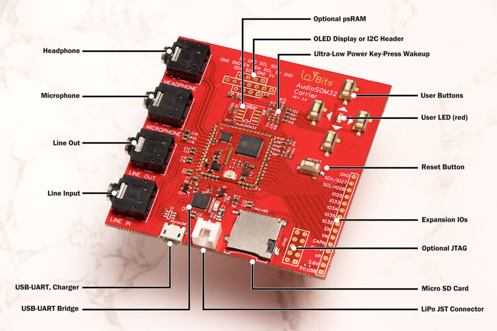
We continue with the introduction of the AudioSOM32 carrier in this ESP32 audio tutorial. The rest of the tutorials in this series will use this carrier board.
A brief list of AudioSOM32 carrier features

The AudioSOM32 carrier is very versatile and lets you prototype pretty much anything that you have in mind. There are enough spare pins for using with your own custom hardware. Even after making many GPIOs available to you, the AudioSOM32 carrier still exposes all the audio peripherals that are essential to developing an audio application.
The following sections walk you through all the peripherals, in a clockwise manner starting with the USB connector.
1. USB-UART bridge and charger
2. Stereo line IN and line OUT (3.5mm jacks)
Stereo line input and line output are provided for external audio equipment interfacing via two standard 3.5mm audio jacks.
The line inputs and outputs are compliant with recommended audio line input and output specifications. The line jacks can accept or output 1Vpp audio signals that almost all audio equipments work with.
Line input and output are both coupled using a DC blocking capacitor of 1uF. This rules out presence of any high voltage DC components or offset at the line input and output.
3. Microphone input with programmable mic bias (3.5mm jack)
The microphone input is a mono input (the SGTL5000 codec only offers a mono microphone input). For using stereo or multiple microphones, it is recommended that you use the stereo line input terminals.
What is special about this microphone input is that it provides a programmable microphone bias voltage. You can vary the bias voltage for best results and directly connect condenser or analog MEMS microphones to the mic 3.5mm jack.
Note that the microphone input is decoupled with DC blocking capacitor to prevent a DC bias. If you want to use a high microphone bias voltage for some reason, you should use the line input terminals for that instead.
4. Stereo headphone output (3.5mm jack)
5. Optional pSRAM
6. Flexible OLED display or I2C bus header for sensors
These are several headers with I2C bus and 3V output that can be used to interface with sensors or an external OLED display. The pinout of the headers is made to fit with most common OLED modules available in the market so you do not have to do any manual wiring to add I2C displays to the AudioSOM32 carrier.
You can also add accelerometers, light sensors and other external hardware to these headers.
7. Ultra low power user keys and LED
The ultra low power user keys are 4 keys that can be programmed and read by the ESP32 using 1 analog GPIO only. The keyboard is capable of waking the AudioSOM32 up from deep sleep via an external interrupt when any of the keys are pressed by the user.
This makes the keys extremely useful in prototyping ultra low power battery operated applications using the AudioSOM32 carrier board.
The LED is directly driven by the ESP32 in AudioSOM32 module and can be used to indicate recording or playback, etc.
8. GPIO expansion header
The GPIO expansion header lets you use the buttons status and interrupt for external hardware. It also lets you use the codec I2C bus for interfacing to external hardware.
All the other pins are spare GPIOs that are free to use in any way that you would want to. They are labelled for easy use during development.
9. Optional JTAG and high speed micro SD card
The optional JTAG port can only used when SD card connector is empty and unused. This is a hardware limitation of the ESP32 chip and therefore you cannot use both JTAG and SD card 4-wire mode at the same time.
If you plan on using the JTAG interface, we recommend using VisualGDB for Microsoft Visual Studio. Eclipse is a little difficult to configure in our experience.
Finally, we hope that you found this tutorial or walkthrough helpful!
The AudioSOM32 carrier fully makes a ton of audio features available while working with a LiPo cell consuming less than 100uA in sleep mode. Added support for user-button based wake up makes the AudioSOM32 carrier perfect for prototyping audio applications.
In part 3 of this tutorial...
In the next part, we look at the schematics of the AudioSOM32 module and how the ESP32 and audio codec are connected or interfaced.
You can find Part 3 of the ESP32 audio tutorial series here:
Introduction to AudioSOM32 carrier – ESP32 audio tutorial #3
We only mail you less than 2 times a month.
Change Log
- Initial Release: 22 January 2021
References
- Reference 1: AudioSOM32 carrier board, development kit
(IoTBits page, now managed by PCB Artists).